The MGA With An Attitude
MGA Guru Is GOING MOBILE - (November 16 - November 30, 2023)
Thursday, November 16, 2023:
Mostly a day off. Kind of a haze, don't remember doing much useful, aside from answering a few tech questions. Looking forward to receiving parts and machined block, picking up oil and filter, anti-freeze, gear oil, and paint.
Friday, November 17, 2023:
Some good news and bad news. Good news is, parts to put my engine back together arrived today. Bad news is, the engine machinist didn't get the sleeve installed yet, and he is going on
 vacation next week. So we will be grounded for an additional 10 days. Not going to get the car back in service until maybe December 6.
 Spent much of the day editing, spell-checking, and re-composing a document Service and Repair Manual for Andrex Friction Shock Absorbers (2.4-MB file). Got that uploaded to the Suspension Tech pages before midnight. Spent much of the day editing, spell-checking, and re-composing a document Service and Repair Manual for Andrex Friction Shock Absorbers (2.4-MB file). Got that uploaded to the Suspension Tech pages before midnight.
Saturday, November 18, 2023:

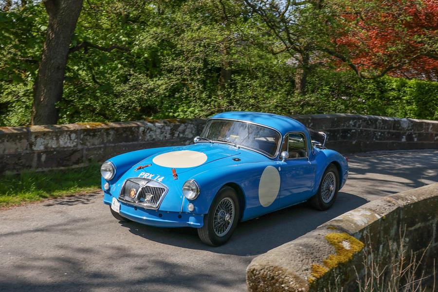
Some chat about how to install an early MGB gearbox in a late model MGA (not as easy as you might think). Someome's clutch issues with first start-up of a project MGA. Some addendum to a tech page on choosing the best final drive ratio, and listing of overdrive and 5-speed overdrive ratios. Some update to the Variants tech page for PRX 14. Yes, it lives on. -- The best part of my day was watching and reviewing the launch of Spacex Starship flight test 2. What an amazing machine!
Sunday, November 19, 2023:
BBS, email, and a couple of tech questions on clutch chatter and fuel flow issues. More discussion on final drive ratios, overdrive, and engine power relationships. More issues with incorrect ride height with new replacement MGA rear springs (will this 25-year old problem ever be resolved?).
Monday, November 20, 2023:


Spent too many hours with two new Part Number tech pages trying to document two rubber straps AHH5440 and ACH8979 originally used as tie-wraps to secure heater control cables in the MGA.
Tuesday, November 21, 2023:
Uploaded a new document (6-page PDF file) for "B.M.C. Part Numbering System" explaining the numbering system for B.M.C. part numbers, including title/description for each of the Austin 3-character prefix codes. Use this in conjunction with the "Fastiner Decode Booklet for B.M.C. Vehicles" to determine the descriptions for all B.M.C. standard part numbers.
 Trying to pull up a 20 year old CAD drawing, but my old AutoCAD software had been long since extinct. A more recent version of some cheap CAD program was also lost with a computer crash in late 2022. All I want to do is to print the CAD drawing as a full scale PDF document for 48-in x 36-in paper. Been fiddling with several different 2D CAD programs over the past year. I finally bought and paid for QCAD-Professional, and got it installed on my computer. Learning to edit CAD drawings with it, got the desired drawing touched up and saved. But now I can't get it to print the PDF document at full scale. Ran out of endurance at 2-am. Maybe tomorrow.
Wednesday, November 22, 2023:
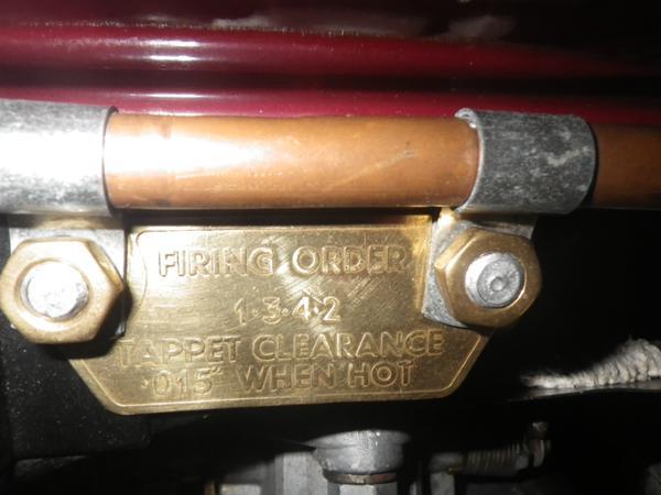
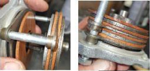
Since August 21, someone was asking about the MGA "ID Plate, Intake Manifold" (Firing Order and Tappet Clearance plate), in particular, where it is to be installed and how to mount it as original. --- While a few people
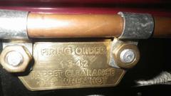 were presenting pictures of the plate and how it is mounted on the engine, we notice there were two different numbers for tappet clearance, .015" and .017". --- While investigating this question, I found two different factory part numbers on the Moss Motors, UK web site. One plate said .015"
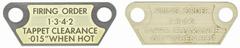 while the other said .017". But both part numbers claim to be for the same spread of vehicles, all MGA (except Twin Cam) 1955-1962. An obvious conflict of information.
Thursday, November 23, 2023:
Happy Thanksgiving (national holiday) for all of us in USA, North America.
Continuing to chase yesterday's questions about intake manifold ID Plates, I looked for these part numbers in the MGA Service Parts Lists (all of these books), and found nothing. These plates are not even referenced in the SPL books. Not faulty information, just missing. --- So I looked in the "MG Series MGA Workshop Manual" (all editions 1955-1965). And I looked in the "MG Series MGA Operators Manual" and "MG Series MGA Drivers Handbook" (all editions). In all of those documents it specifies .015" tappet clearance for all MGA (except Twin Cam). --- So now we know that .017 is wrong. And furthermore, the .015" plate being offered by
Moss UK is in two colors, where the original plate was plain brass embossed, so both of the Moss UK plates are wrong. Pretty sure the .017" plate is for an MGTC engine (not Twin Cam).
After all the research, it must be a good idea to upload a new Part Numbers tech page for the "ID Plate, Intake Manifold" for the known information (including incorrect parts). And I like to place the ID Plate on top of the P-clips, so it looks the same whether you have a heater or not. --- Now we still don't know where to buy a good one, but since it is nearly indestructible embossed brass, there will be lots of good used ones available. Press it flat and buff out any scratches, a good vintage piece with desirable patina.
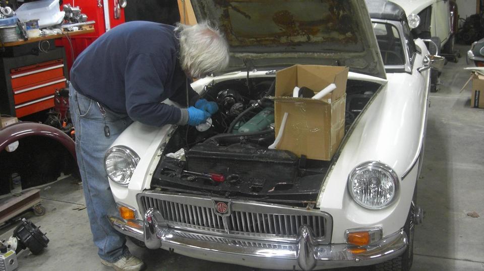
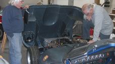
Since we seem to be stuck here for a few more days (more likely another week), I can take a little time to do something else useful. Down to the garage to help out with Micheal's MGC. We began with firing it up to running temperature and adjusting the freshly rebuilt carburetors. While it is common to find these cars running rich, this one was running quite lean, needing at least two full turns of the mixture nuts to set it right. Fortunately that didn't take long, just leaving the choke cable attachment and adjustment for later.
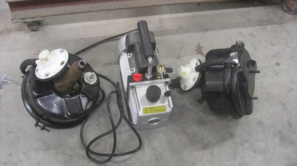
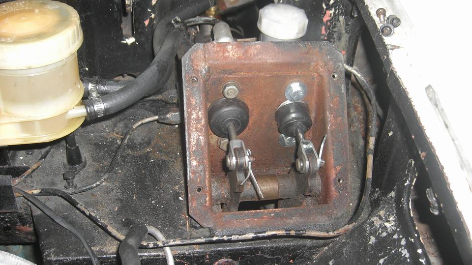
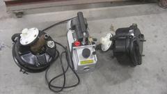
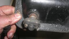
Micheal knew the brake servos were not working. I think he jumped the gun and bought two new (rebuilt) servos before doing the diagnostic work, but it turned out both had failed vacuum diaphragms and needed to be rebuilt anyway. He had pulled out a vacuum pump, but we didn't need it for testing (unless we might want to test the new ones before installation). Just connect a hose to the vacuum port and blow on it (no blow because it has an inlet check valve), and then suck on it (which only makes a hissing sound because it has a ruptured diaphragm). Okay, two bad servos, go ahead and pull them out, two small pipes, one large hose, and two hex nuts in back to release them from the mounting bracket. Assembly is the reverse of disassembly, so not long to get the new ones installed, not even any skinned knuckles.

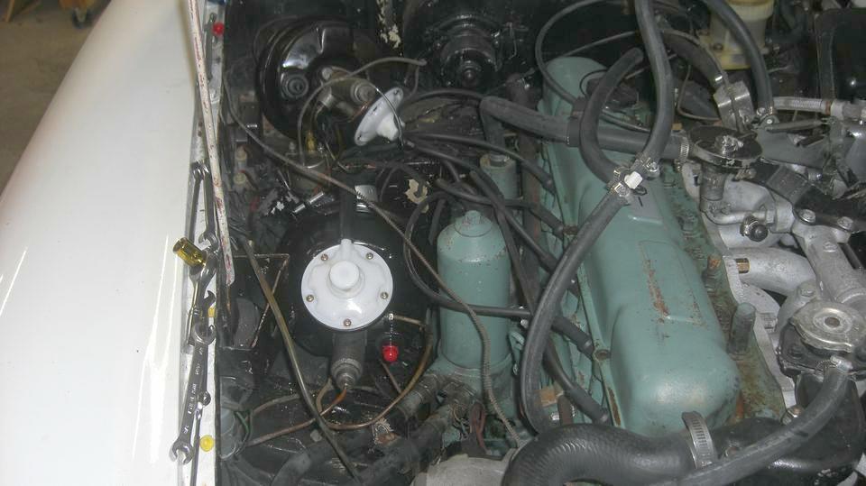
Two pipes and mounting on each one, then the vacuum hoses connected. Then the fun jacking up and crawling on the floor to bleed the brakes all around. Had to suck old dirty fluid out of the reservoir (yuck), install clean fluid, and flush it completely through at all four corners until it came out clean (no bubbles by that time).
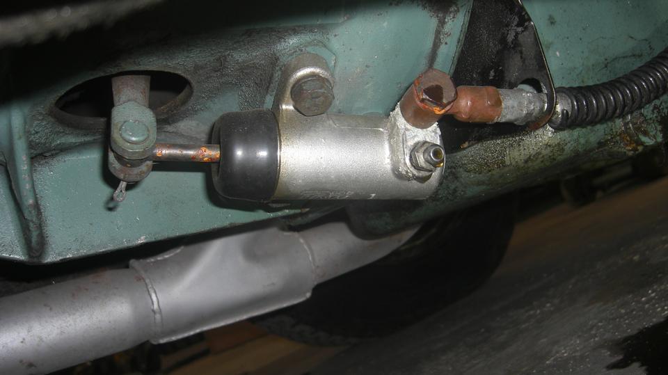
Repeat for the clutch circuit, suck out old fluid, install new fluid. Only about 2 fluid ounce capacity in the clutch master reservoir, so limit this one to four pedal strokes between refilling. Oops, this would not go well with the bleed nipple on the bottom port, so take a few minutes to swap the banjo fitting with the bleed nipple (and lose two ounces of new fluid on the floor because I didn't want to pinch the hose). Soon all was well, clean and tight and dry after bleeding. Did need to finish tightening the banjo bolt to banish the last one drop per minute under pressure with the pedal down. Shhhh, don't tell anyone there is no rubber boot on an MGC release lever. This may be an early MGC with the banjo fitting on the side of the slave cylinder. Otherwise Moss Motors is now pushing an end port cylinder from a variety of Triumphs to eliminate the banjo bolt and banjo fitting.

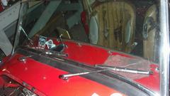
The clutch pedal releases the clutch at about 2/3 stroke, still well above the floor, no problem. No brake lights, to be expected, because there are a LOT of disconnected wires in this car. Wires broken off the switch can be soldered back on, but I want to check the switch to be sure it works first. The switch housing is loose from the threaded mounting collar, so that alone is good enough reason to buy a new switch. Everything under the bonnet has been painted black, so all the wires are now the same color. You might expect some wiring problems when there is a new wiring harness in the boot.
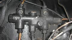
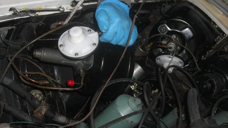
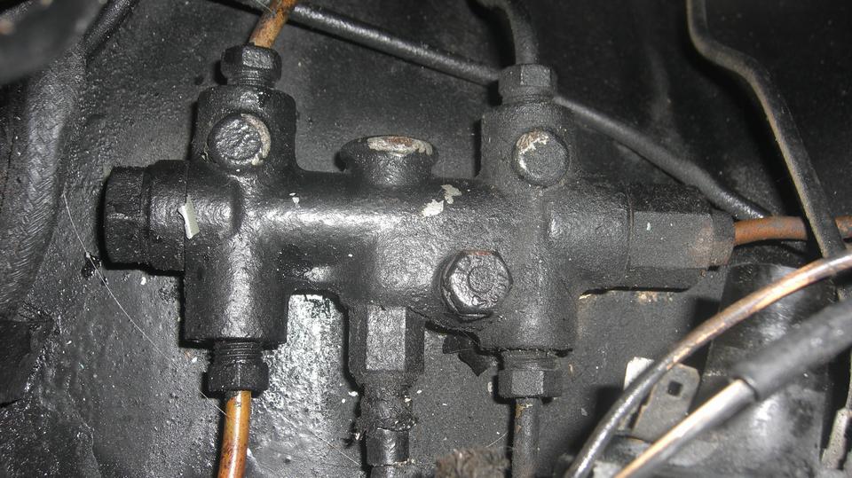
I wanted to test the brake pressure warning switch (in the last picture). For that, open one bleed nipple to kill pressure in one circuit only (front or rear), press the brake pedal, and see if the warning switch lights up on the dash. Tighten the bleed nipple while the pedal is still held down. You should do this test at both ends of the car. The warning light should light up for a pressure failure at either end of the car, and should go out when the pedal is up. If it doesn't work properly, it can be repaired. Take it apart, clean it up, install two new tiny O-rings (5/16" OD, 3/16" ID, 1/16" wide) from a local auto parts store, and put it back together. Out of time now, but we may get back to this car on Saturday. And this was just beginning to be a long day.
Friday, November 24, 2023:
Written at 9-am after pulling an all-nighter. Following yesterday's MGC brake system ventures, I needed to update the travel log. For that I had to process a couple dozen pictures for the web page. That led me to creating a new Brakes tech page for the Dual Line Pressure Failure Warning Switch. Since this was a spin-off from the previous page Dual Line Master Cylinder on the MGA, I had to revise that page as well.
By the time I got all that done, it was "Good Morning Starshine" 1969 (grab your ear buds and crank up the volume before you click here), and I still had to write this last paragraph for the travel log. -- Zzzzzz.
 Hello, still Friday? Our host was out of town today, so we got to sleep in (like 9:30 am to 2:30 pm). A few hours
later we headed to the garage to drain and change oil in the gearbox and differential, and give it a lube job. Just a bit of a formality, and it's just maintenance.
Hello, still Friday? Our host was out of town today, so we got to sleep in (like 9:30 am to 2:30 pm). A few hours
later we headed to the garage to drain and change oil in the gearbox and differential, and give it a lube job. Just a bit of a formality, and it's just maintenance.
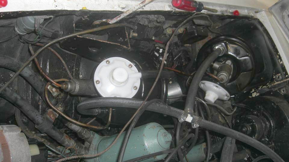
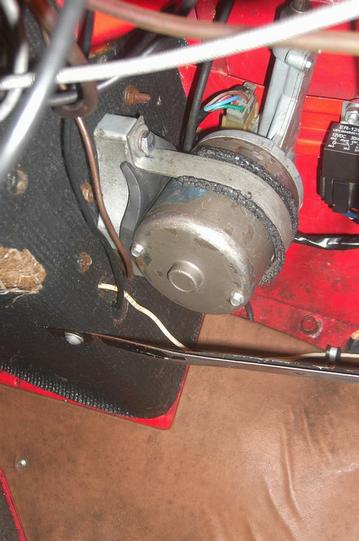
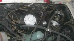
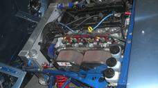
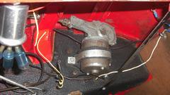
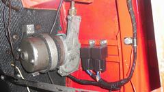
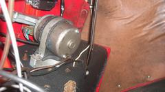
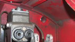
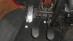
Then we got started on a project I have been wanting to do for many years, swapping the "PITA for
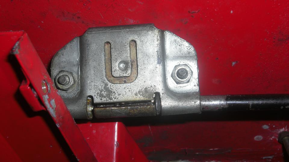
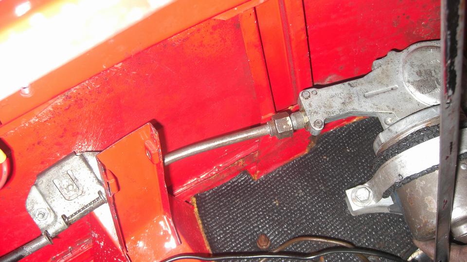
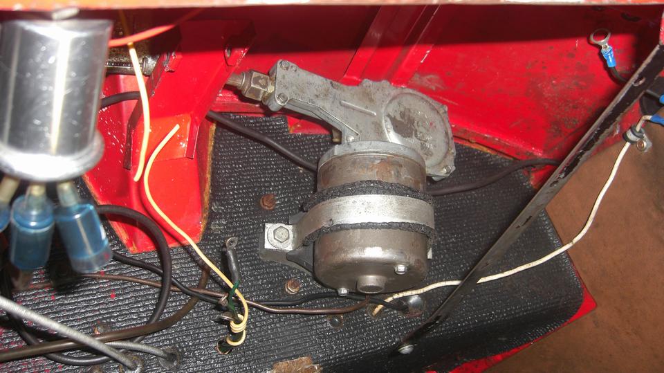
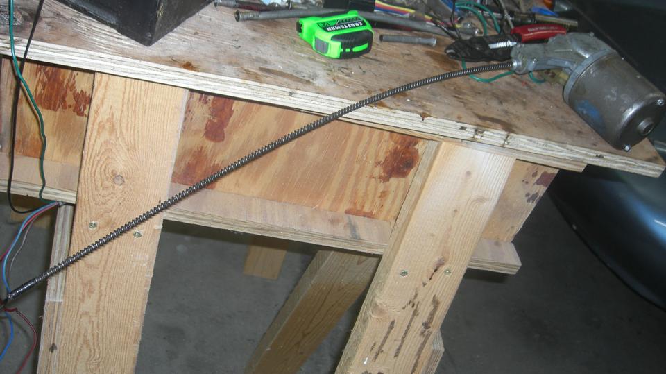
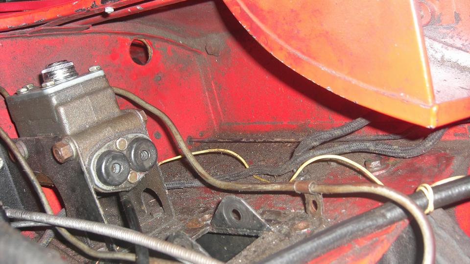
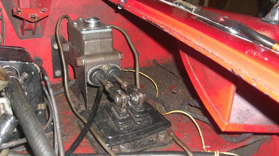
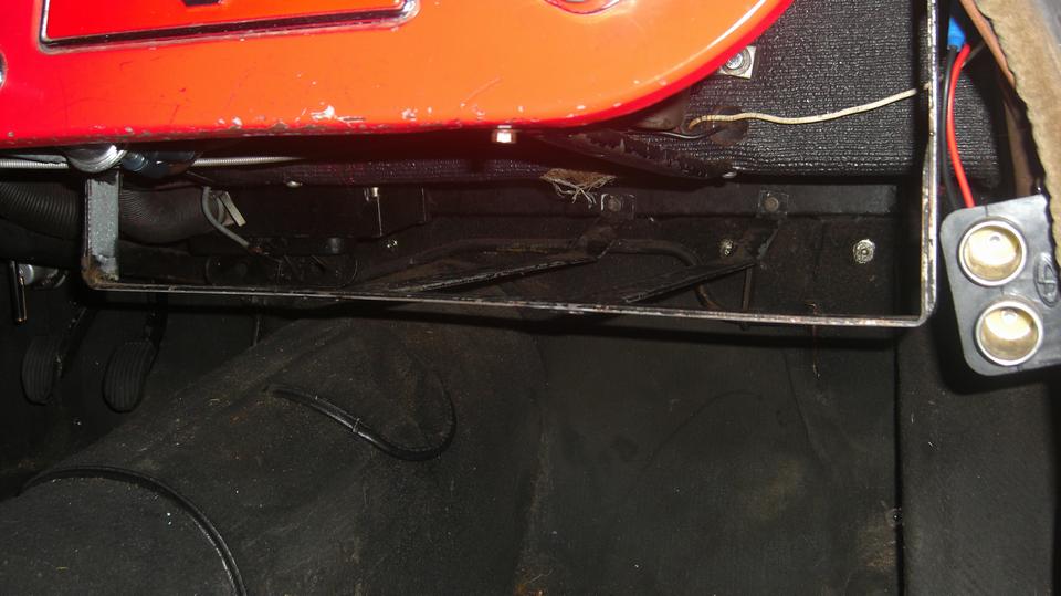
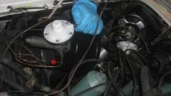
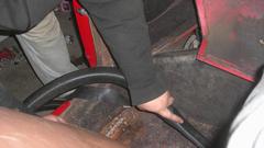
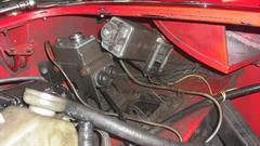 maintenance" single speed wiper motor behind the master cylinder to a 2-speed wiper motor behind the firewall on opposite side of the car, where it would be much easier to service. First picture illustrates why I want to get rid of this thing. To get it out of the car for service you have to remove the master cylinder push rods, and the rubber pedal excluder boot, and the pedal pivot bolt, and drop the pedals on the floor. Then remove the wiper arms, disconnect the drive pipe from the wiper motor gearbox, and pull the drive cable out of the pipe while watching the wiper spindles spin around.
Next was to remove the demister vents and cowlings and flex pipes under the dash to have access to
 the wiper wheelboxes. Removing clamping screws from the wheelboxes disconnects the drive casings, after which the wheelboxes can be removed. Beginning to sound like disassembling half the car for this job, but not so bad after you do it a couple of times and know the right puzzle combinations. Now I didn't think the MGB wheelboxes would fit here, but surprise, they did (barely). The trick is to use the MGA underside spacer tubes, and the MGA top side chrome bezels, so the spindles end up on the same angle perpendicular to the windscreen.
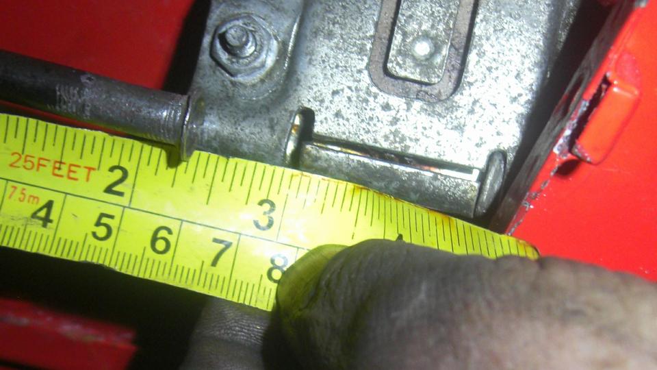
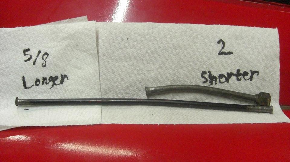
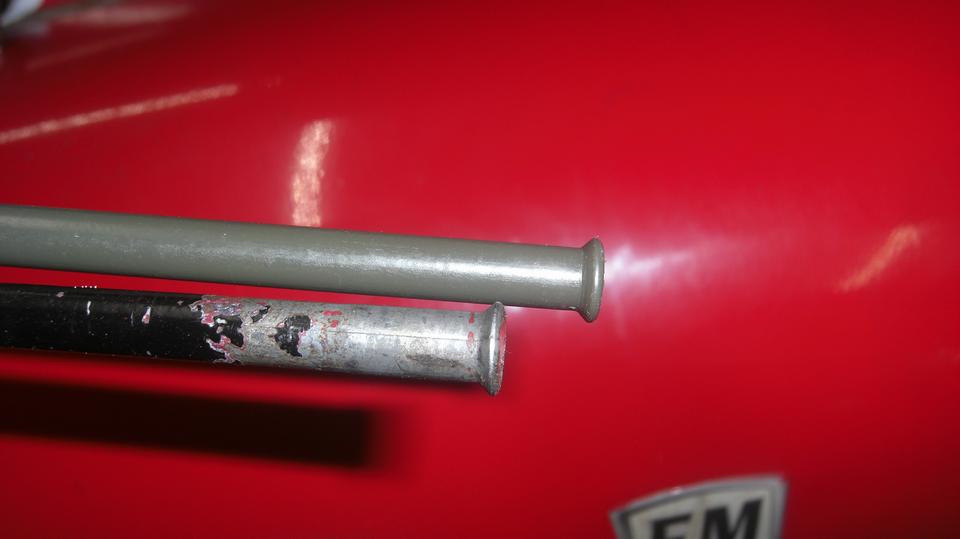
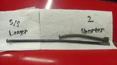
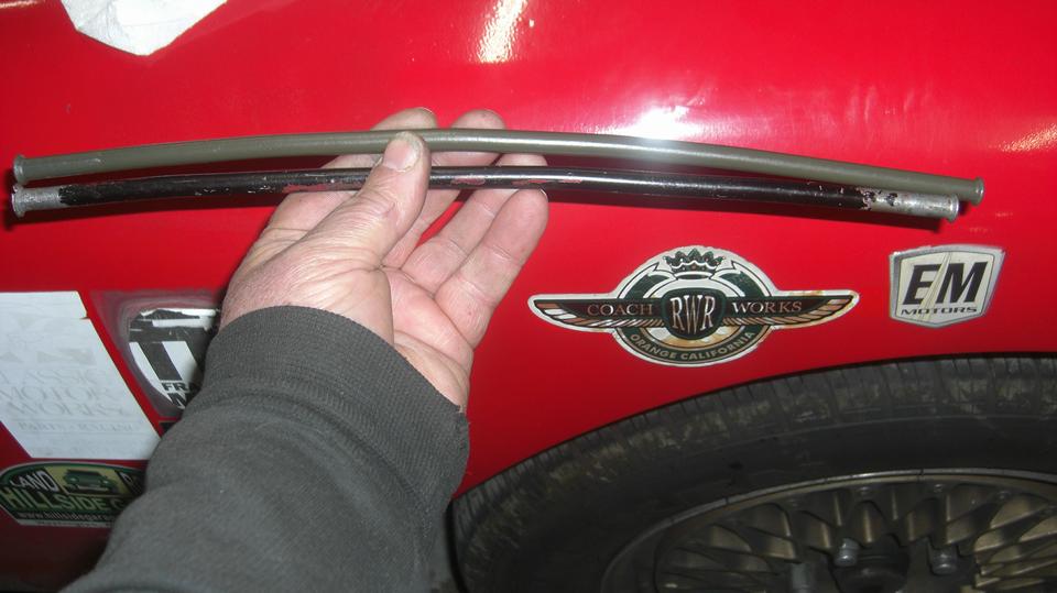
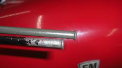
The MGA and MGB wheelboxes are sightly different design, so the drive casing overlap is different, as well as the center casing being different length. I clamped the MGA casing in the left side box, and laid the other end near the right side box for comparison. After careful measurement, we will need to make another center casing 5/8-inch longer (or maybe a hair more).

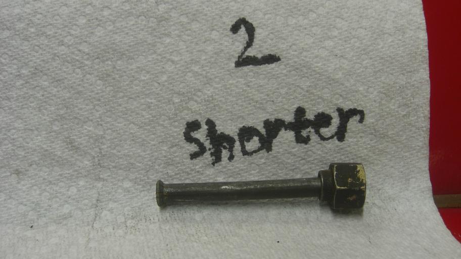
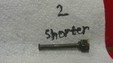
 I installed the MGB input casing into the right side wheelbox, and shoved the MGB motor drive cable through it until full abutment. The MGB wiper motor "had its back to the wall", so to speak, so I plan on shortening that drive casing by two inches to put the motor in a more reasonable position for easy access. In the end it may get even closer yet. About that time navigator mentioned that it was well past midnight again, so we should knock it off for the night. But by now I had a good feeling that this was going better than I had anticipated.

Saturday, November 25, 2023:

Not recovered from short sleep yet. A bit of trivia. Just posted a new tech page under Literature for MGA, Advertising, Vintage, Non-MG, showing some vintage ads for Brylcreem (featuring MGA of course). They were giving away new MGA, lots of them, or a live tiger if you prefer.
Took a short trip to a local parts store to buy some 5/16" brake pipe to make new casings for the windscreen wiper drive. -- After the common formalities of being MGAguru (BBS, email, tech questions, etc), I just had to get to bed before midnight this time.
Sunday, November 26, 2023:
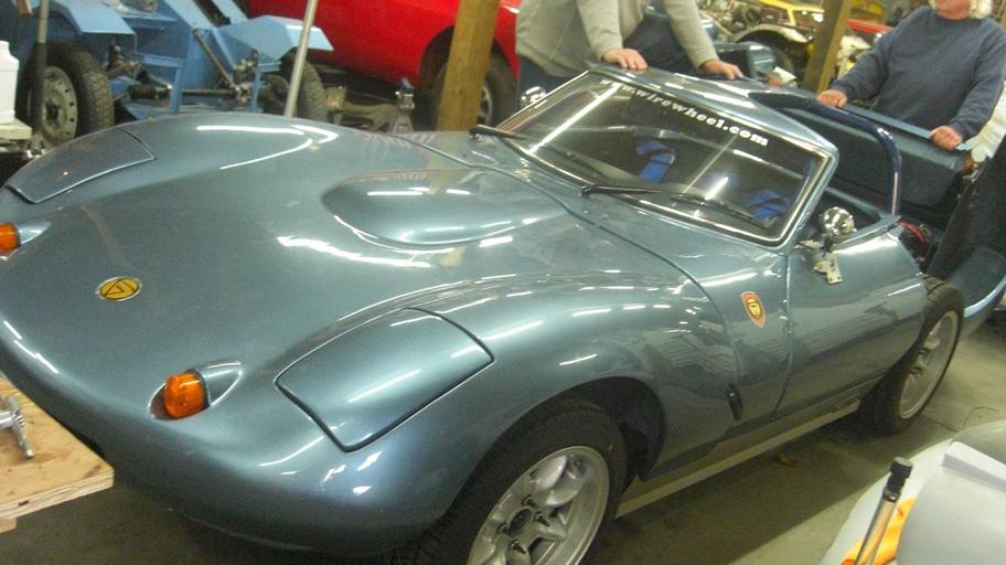
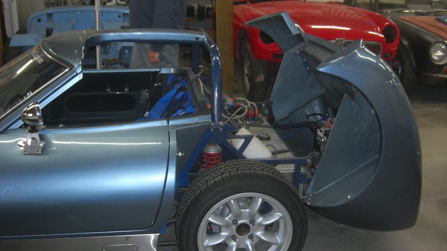
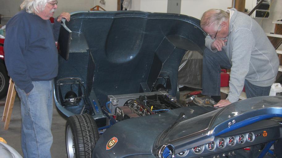
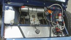
A friend of our host came over to discuss the ongoing work on his MGC, repaired vacuum leak, tune-up, and new brake boosters. While he was there we got a closer tour of the Ginetta G4 series IV, thinking there may be only two of this model in North America. Cute the way the tail clams open for easy service access in the back. Tube frame and fiberglass body for minimal weight.
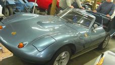
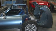
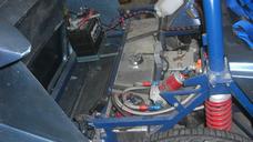
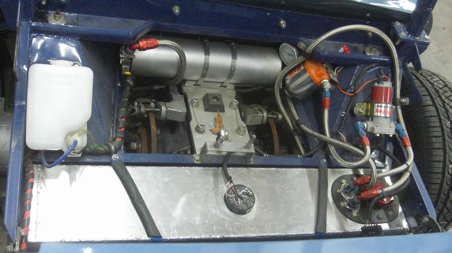
Fuel cell, fuel pump, Accusump for pre-oiling before start, considering that the engine is dry-sump. The rear differential with inboard disc brakes is from a
Jaguar E-type. Up front,throttle body fuel injection.
After company left we were reviewing the MGB 2-speed wiper motor transplant on my MGA. We now have
 the required relays to wire it up using an MGA headlight switch in place of the original wiper switch, so I was getting a little more enthused about the mechanical installation. A small temporary snag when the 5/16" brake pipe I bought yesterday turned out to be 3/8" pipe, so that will need to go back for exchange tomorrow. Not able to lengthen the center casing yet, I was soon shortening the input end casing for final positioning of the drive motor and gearbox drive. All this custom stuff is rather slow going, time consuming, but it's getting there.
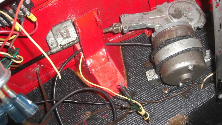
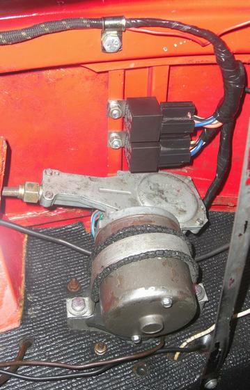
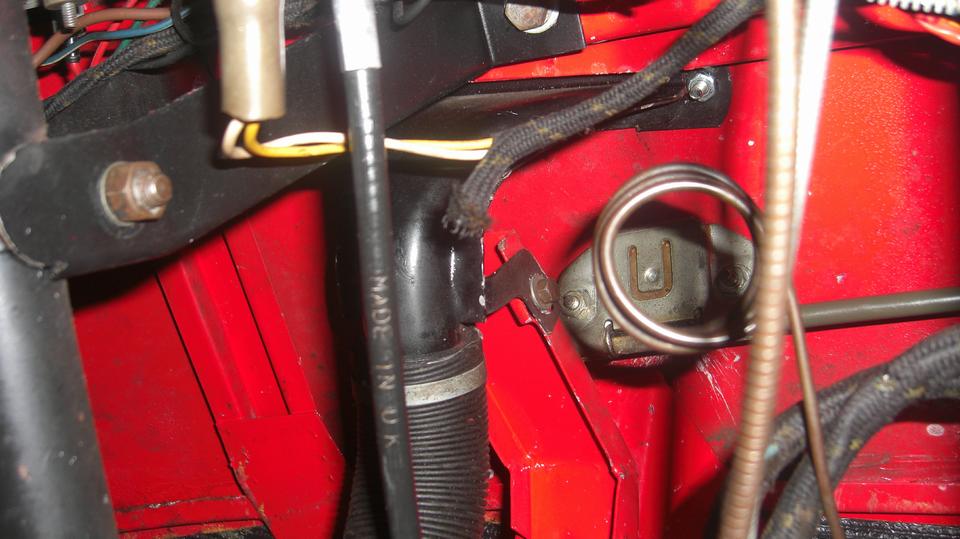
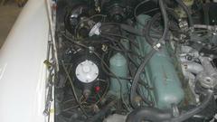
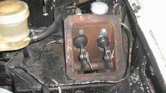
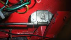
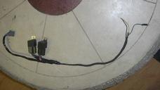
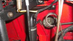
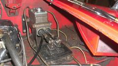
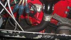
 For each small step forward there is a change of plans with on the fly development. Flipping the wiper motor 3-wire harness branch from left to right. it was just long enough to get through the firewall where a RHD pedal box would bolt in. I also ran one additional wire from the wiper switch area, along the main harness, through the firewall, along the wiper motor branch of the harness, and back through the fire wall along with the original three wires for the motor. Those four wires (at bottom of the picture at right) are power, ground, and two switched wires.
 The switch is only a foot away from the motor (the two switched wires), fused power and ground are on the back of the fuel gauge, so it will be very easy to take the short cuts with the wiring behind the dash, and abandon the original wiper motor wires running through the engine bay (for cleaner installation). So now I plan on installing a barrier strip (similar to the one showing at right, top left corner) as a wiring center along with two DIN style relays (may need to make a simple bracket for the relays). 11-pm, so knock off and take this up again later.
Don't recall if I mentioned what was making me feel good about this progress. Since the MGB wheel boxes did physically fit (with the MGA mounting hardware), the MGB wiper motor can be used as is with no need to change the crank wheel in the gearbox.
Monday, November 27, 2023:
Early morning trip to return the 3/8" brake pipe in exchange for a proper 5/16" pipe. Then a trip to the machine shop to check on my engine sleeving job. Owner back from vacation, and he has someone machining out the old sleeve today. At least the machining is finally in process. Then off to Lowe's to pick up some longer mounting bolts and a few simple tools. Going to be here at least a few more days, so a side trip to Walmart for some groceries. Some time to catch up BBS and email. In the evening logged into John Twist's Zoom tech session, after which it time to catch up on sleep.
Tuesday, November 28, 2023:
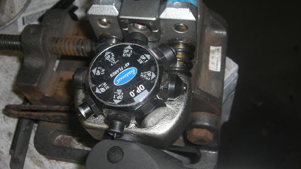
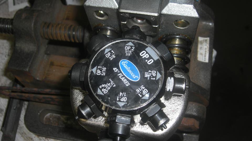
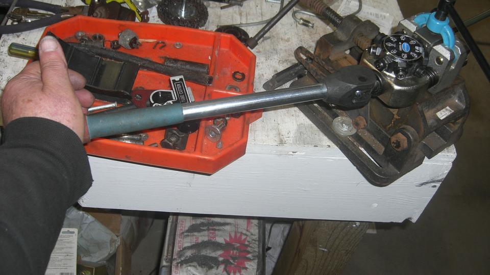
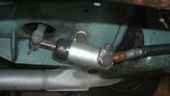
Had a touch of snow over night, so a cold garage today, but tolerable. Back to work on the MGB wiper motor installation. Let's make up that longer center casing for the wiper drive. Michael has this nifty bench mounted tube flaring tool, and boy is it sweet. Select the matching 2-piece collet, place the tube end flush with end of collet, flip the top clamp over, pin it in place, and wind down the clamping screw. Spin to select the first punch OP.1 5/16, and give the cam handle a 90 degree push. Spin to select the second punch OP.2 5/16, and give the cam handle another 90 degree push.
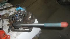
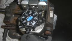
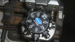
Release the top screw clamp, and extract the tube with the perfectly finished flare. Exactly 5/8" longer than the old center casing, and a perfect fit between the wheelboxes.

All wheelboxes and casings installed, time to fit the motor/gearbox and drive cable. Seemed like a good idea to hot wire the 5-pin connector on the motor to be sure we had the circuits right before putting it in the car.
 Black ground wire and Green power wire clamped to posts of test battery. Touch Red/Green to power to run in low speed. Touch Blue/Green to power to run in high speed. Works great. To make it run to Park position and stop, get it running in low speed, then disconnect Red/Green and touch it to Brown/Green. Just a little tricky doing this with your fingers. When running, the Park switch is connected to power. Moving Red/Green from battery to Brown/Green has Red/Green still connected to power, still running in low speed. When it gets to the Park position, the Park switch changes from power to ground. That shorts the low speed circuit to ground on both ends, making a very effective electric brake, so the rotor stops instantly (like it was hit with a hammer).
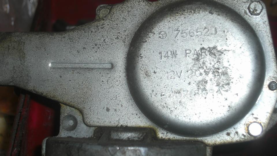
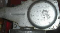
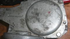
We have two of these MGB permanent magnet wiper motors, intending to install one and keep one as a spare. They both tested good, work fine. The 75652J motor parks with the cable extended. The 75697A motor parks with the cable withdrawn. This setup needs to park with the cable withdrawn. The 75652J also runs a bit faster, might be preferred,but the park switch is buried inside, not easy access to change it, so we set that one aside and installed the slightly slower one.

Wiper motor installed in the car (with drive cable reduced to appropriate length). Good time to knock off for the night, to go after the wiring (and relays) tomorrow. I took the original two terminal wiper switch out of the dash, ready to install a three terminal lighting switch in its place. Then we couldn't find the spare lighting switch. Inventory list says we still have one, so will have to look again tomorrow.
Wednesday, November 29, 2023:
Yesterday's snow didn't seem too bad, but today we arose to the toilet and adjacent sink not running due to a frozen water pipe (15dF in the small hours of the morning). Fortunately that thawed out by 11-am, all is well there.
By 10-am I as in the (rather cold) shop doing layout for positioning two relays for the two-speed wiper motor. This had changed plans several times, finally decided no sub-plate needed, and do not attach to the motor. Drill two holes to mount the relays close to the wiper motor. The motor has a 5-wire branch cable. Another 3-wire branch will be running behind the dash for power from the fuel gauge terminal and two signal wires from the wiper switch. All of the new wiring is going to make a second dash harness (or screen wiper harness) with the two relay sockets in the middle.
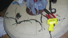
Wiper motor and two relays plugged in. The original 3-wire harness branch for the wiper motor is cut off of the main harness in engine bay (behind the heater box) to be relocated behind the dash (because none of the new wiper wiring will be in the engine bay. I pulled the black wire out of the original 3-wire branch, end pushed in a new yellow wire (not to confuse anyone in the future with a funny black wire that would have been the new high speed signal wire). Then massage all of the wires to where I want the new harness to lie, and tape the wires to maintain the final shape. Then unplug everything, and take the new harness model to the "warm room" for final construction work.
11-am, there it was on the table with motor connector on the left, relays in the middle, the power input and signals branch on the right. Five hours of being very careful to get it right the first time had it finished and taped at 4-pm. The black motor grounding wire is trying to hide, barely visible as a ring lug just below the left relay socket (after taping).
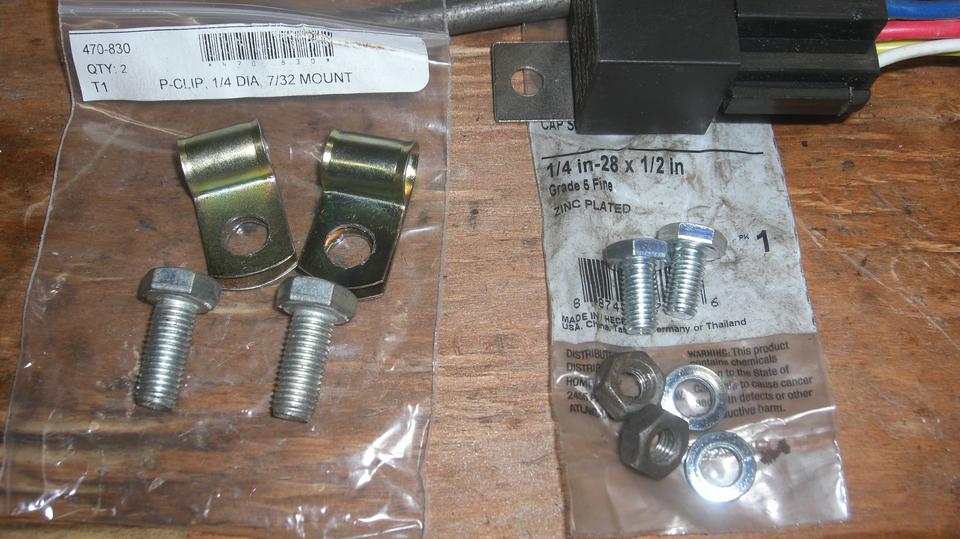
All of the wire junctions in this harness are inside the fat spot just to the right of the relays. All junctions are soldered and shrink wrapped (before taping). Just to right of the tape is the original cloth covered harness piece (3-wire) that is being transplanted from the engine bay into this cable. Two P-clips will secure the harness, while the smaller bolts are for the relays.

 This is the wiring logic diagram used for all of the soldered connections in the new harness. The single speed wiper switch has been changed to a "Lighting Switch" to provide three positions for off, low and high speeds. All of the circled 12V wires are soldered to the single input power supply wire. One key feature is the motor park switch which connects to power when the motor is running. When switching off, the park switch will connect to to ground when it comes to the park position. That grounds both ends of the rotor circuit to make an electric brake so it will stop instantly at a repeatable position.
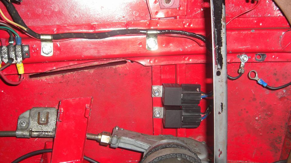
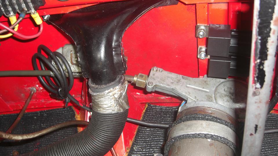
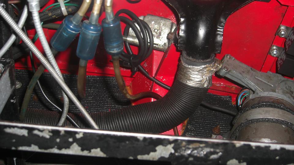
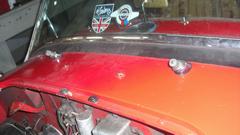
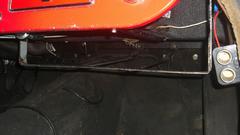
Whomp, thar it is! All installed in the car. The relays are bolted to the under cowl body brace. The P-clips (in the space above the radio) are bolted into captive (hidden) float nuts originally provided for RHD steering column bracket. As a bonus, the single red wire for the map light switch is now secured by the same P-clips. The last unsecured black ground wire (for the cigar lighter power plug) will be attached when the "Navigators Desk" is re-installed. The motor plug is manually accessible just behind the wiper motor gearbox.

First time switched on it didn't run, due to a broken wire at the R1 relay socket (aggressive taping), which we
 fixed. Second time switched on it didn't run, because I had the original signal wire connected to the dash switch instead of the new signal wire (same color code), which I also fixed. Third time switch on it ran like a champ. Good torque, nice full wiper motion with good overlap in the center, little or no backlash at ends of stroke, and not running past the edge of the glass. About one cycle per second on low speed, very much faster on high speed. As designed, it parks instantly in very repeatable manner. I'm stoked! Great way to end a modification job (8-pm).
Thursday, November 30, 2023:
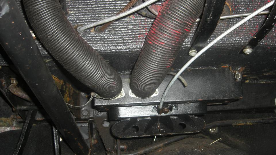
Today's task would be to reassemble everything we had to remove from the car to R&R and modify the windscreen wiper drive. Start with reinstalling the demister ducts. The top screws securing the chrome vents and ducts are a pain. With the windscreen in place this requires use of a right angle ratchet Phillips screw driver, while the little lock washers and nuts underneath try to hide above a body cowl brace flange. Reinstalling the small duct hoses was easy, as long as they had not been damaged in the process.

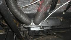
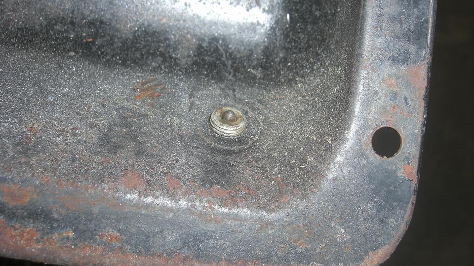
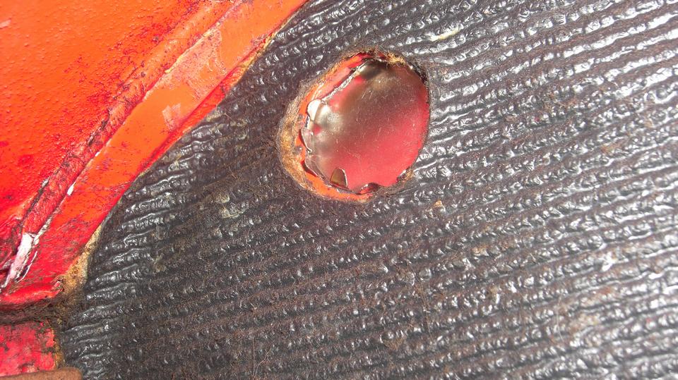
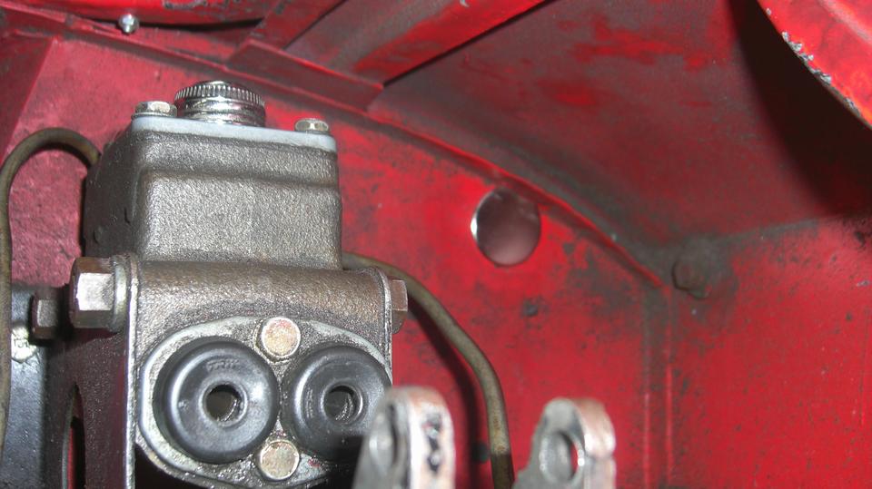
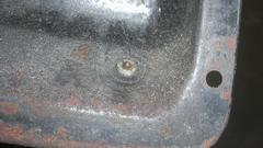
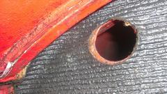
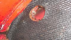
 We should plug a few holes in the firewall and heater shelf left over where the original wiper motor had been deleted. The 1-1/4" hole high in the corner of the firewall where the drive casing used to pass was tricky. A local home store only had a chrome plug that size, no rubber or plastic. Then the large hole was smack up against the top flange of the firewall, so I had to grind a flat on one side of the metal plug. That was not a great fit, so have to redo that plug again later. Also two 1/2" holes remaining in the heater shelf from removal of the wiper motor mount bracket.
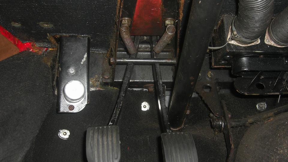
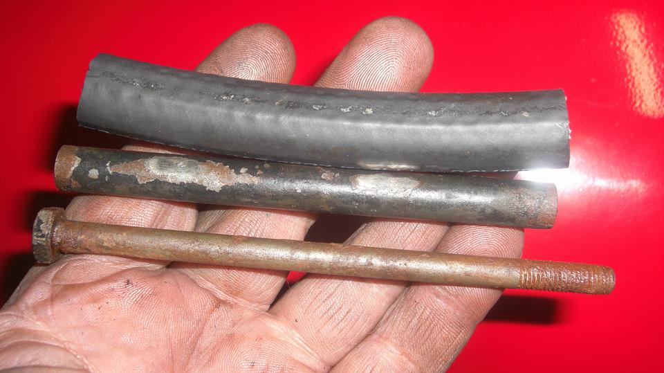
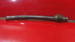
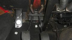
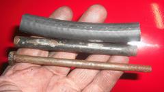
 Reinstalling the pedals and draft excluder boot and retaining ring. This finally nudged me into installing a part that had been missing for 37 years. Below the shelf the pedals have a mechanical upper limit stop consisting of a long 1/4" bolt with a 3/8" tube spacer around it. Around that should be a 3/8" bore rubber hose (5/8" OD). This sent me around the block to the local NAPA store just before closing to pick up a 4-inch piece of 3/8" hose. With that installed, the pedals have a softer and quieter landing when released. This also required shortening the master cylinder pushrods a bit.
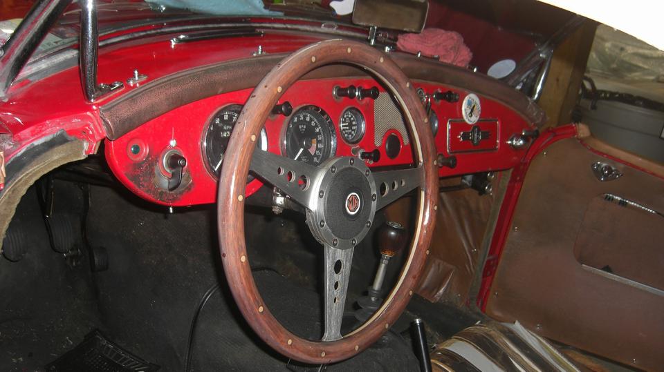
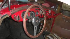
Time to reinstall the steering wheel (be sure to get that pointing straight and level). The blue plastic tube things are (3) aquarium check valves installed in the fluid lines to improve operation of the manual screen washer pump. Finally we reinstalled the Navigator's Desk bracket. That was first installed before the Alaska trip in 1997 thinking it was going to be a temporary gadget. Navigator was eight years old at the time. He didn't go on that trip to Alaska, but he did take an immediate liking to the desk for holding maps and route instructions during road rallies, so it became a permanent fixture. We now have a Garmin GPS, so no more maps, but it still gets used for an occasional rally, and it makes a great storage shelf for his computer.
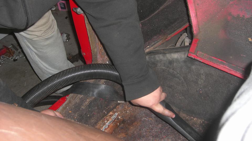
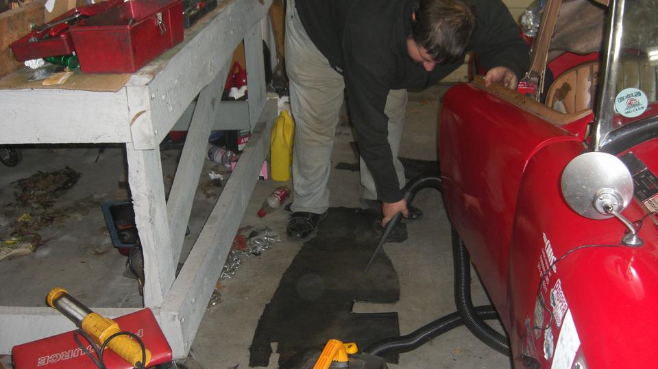
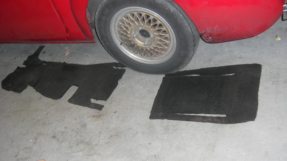
Then on my insistence we pulled out the floor carpets to vacuum out the cockpit, which hadn't been done since Hector was a pup. Being a little damp under there, we left the rugs out to dry over night (maybe if we're lucky).


|