The MGA With An Attitude
Friday March 16, 2018:
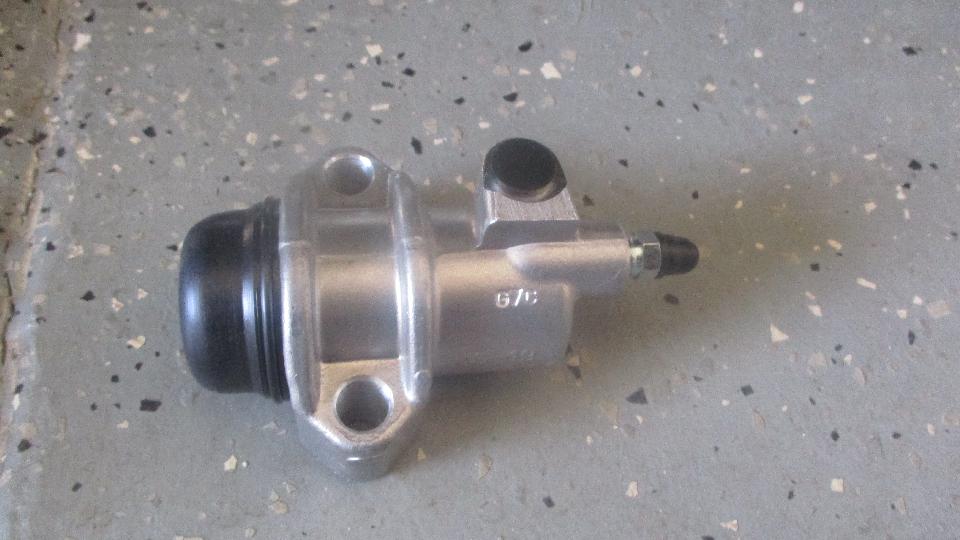
Saturday March 17, 2018: Time catching up with photos and notes for the past few days, and a bunch of waiting email. One question on fuel line fittings led to some research, and it looks like there will be another day required (sometime) to make a new web page for all of the fittings required to fabricate and install MGA fuel lines from tank to pump to carburetors. Sunday March 18, 2018: Some time spent making a list of parts to order for Dave Daniel's MGA and TD, and for George Lawson's MGA, and to restock my trailer. Also bit the bullet and decided to buy a Lucas alternator for my MGA to replace the (spur of the moment makeshift) Mitsubishi alternator that has been bugging me for more than 10 years. Took some time to make (at least start) a CAD drawing for a spring for the MGA Coupe door latch. Not available, so someone should make this part. More time looking forward to possible visits in North Carolina a few days hence. Mapquest is a slug, a royal PITA, and stuffed with pop up ads that take up too much screen space. I spend more time playing Whack-A-Mole there than I do getting any work done. Does anyone know of a better trip mapping application? Sometimes free is not such a good deal. Monday March 19, 2018: Time updating the CMGC web site for upcoming event announcements for the new driving season. It's a long list, likely to kill the whole day. Otherwise, it's funny how many backlog items I find to do when I think I may have a few hours available. Bunch o new parts got ordered today, ollowedby an email announcing the shipment. Tuesday March 20, 2018:  Start the morning off with a little assist for a '57 Chevy with a dead battery. Piece of cake, fired right up. We hauled out of the parking with the Chevy right behind, and then our ignition faild and left us on the side of the road (without the Chevy). Wednesday March 21, 2018: Didn't seem like much done today, but .... We had the car in for the oil change, and I replaced the condenser. Now we need to run it more to see if the problem really is cured. Thursday March 22, 2018: Off to visit Dave Daniel in Lexington, South Carolina. This was our shipping point for several hundred dollars worth of parts for four different cars plus some spares. We got parts for Dave's MGA, for Dave's MG TF, for George Lawson's MGA, for my MGA, and some spares for the magic trailer. Dave's MGA was up first, needing to replace the leaking clutch slave cylinder. That didn't take too long (remembering to relocate the new bleed nipple from the end port to the side port during installation). This is the less expensive aftermarket part, one that used to have a troublesome aluminum piston, since corrected, now having a proper steel piston. I also picked up an extra one for a spare. Two-man bleeding took about 30 seconds, and it works fine. 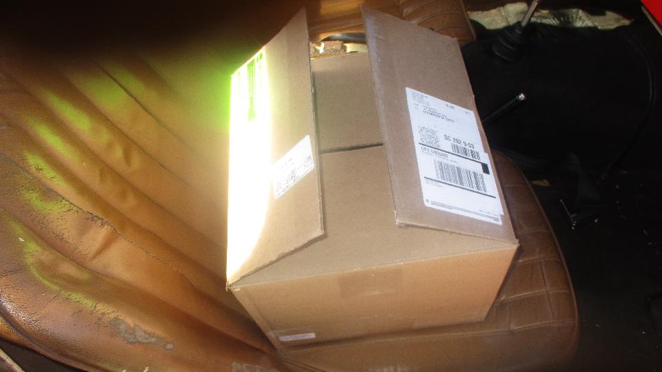
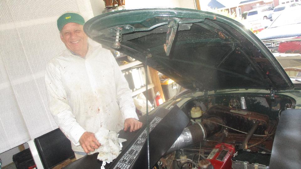
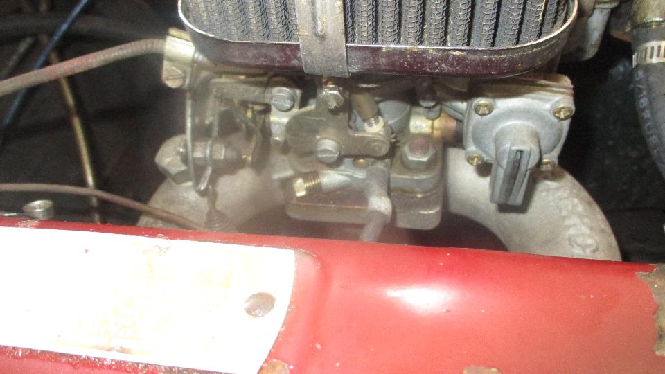
 Thought it was a good idea to change the engine oil, since it had not been done since Dave purchased the non-running vehicle two years earlier (and no one knows how long before that). The stuff came out like black molasses, yuck. New filter and fresh oil was way overdue. Toss one used oil filter and one used slave cylinder (that didn't hold a rebuild kit for 600 miles). For sure the engine is as happy as the look on Dave's face. While it was warming up we adjusted and snugged up the (loose) throttle cable and tweaked the fuel mixture on the Weber carburetor, and it seems to run quite well. 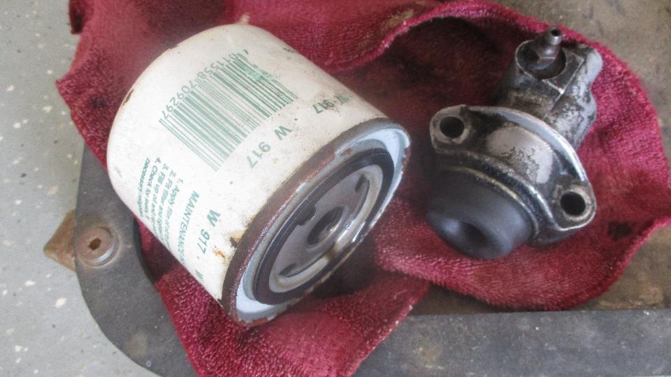
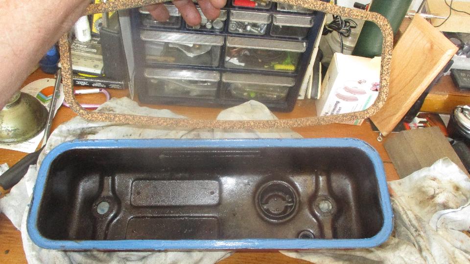
 Time enough to change a leaky valve cover gasket, and the rubber grommets on top. Glue the cork gasket to the cover, and oil the botom side of the gasket, ant it will be re-useable for some years. Dave learned how to adjust the valves in the process. Dave couldn't resist taking it for a test run (okay, we). Apparently taking the slack out of the throttle cable was a big improvement. Yee-haa!. 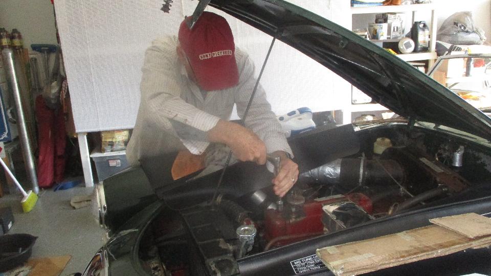
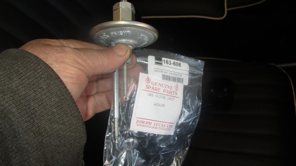
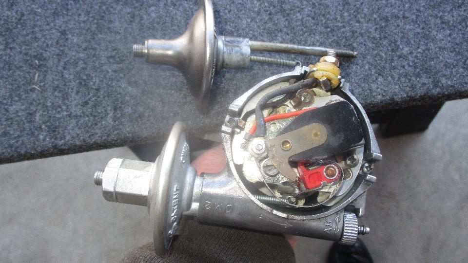
 Friday March 23, 2018: Back to work in George Lawson's MGA today, beginning with replacement of the failed (aftermarket) vacuum unit on the distributor. Scratch the base of the distributor for a timing alignment point, and pull the distributor out for easy access. Rather surprised to find the new vacuum unit is a genuine Lucas part made in England, nice original configuration with all original markings. 
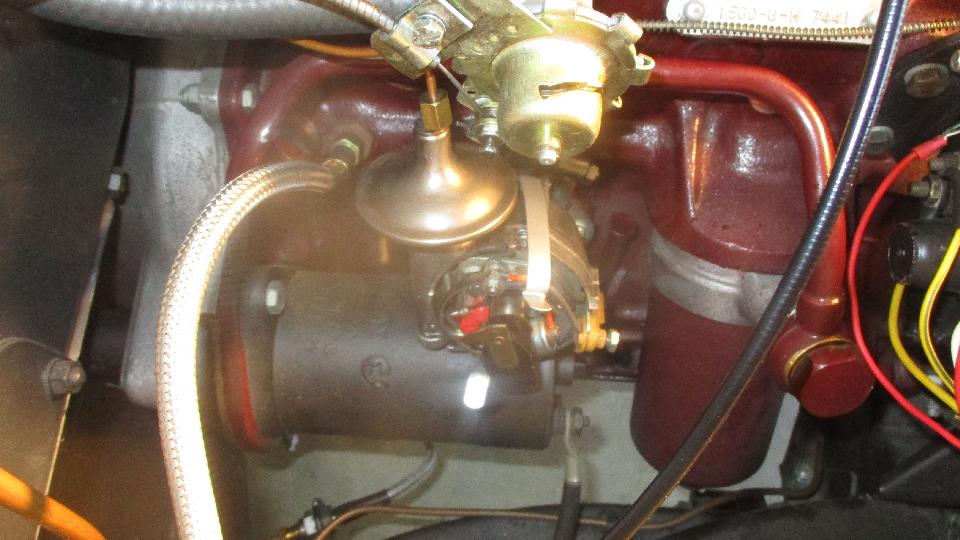
 At first the original fine adjustment nut only screwed on two turns and stuck. After carefully checking for thread match, I had to force feed it up and down the spindle a few times, after which it loosened up enough to turn with fingers only. Not long then to get it back together and back in the car. We also replaced the damaged HT connector nut for the original type ignition coil. 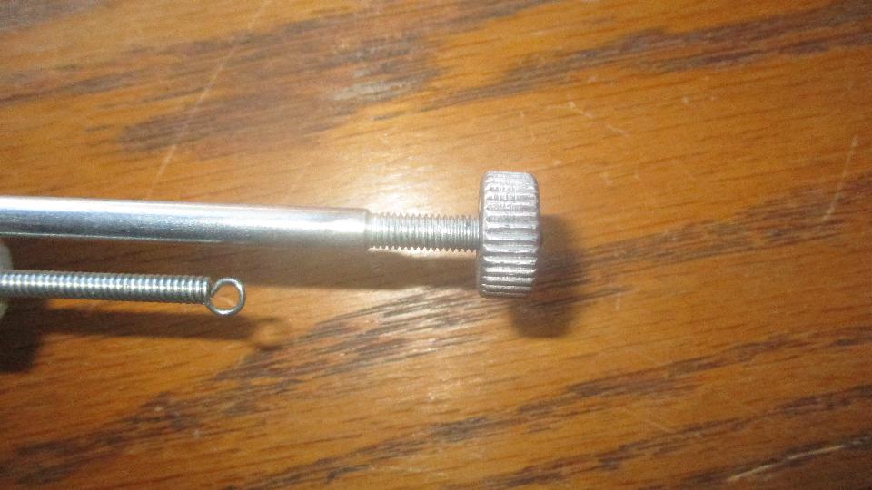
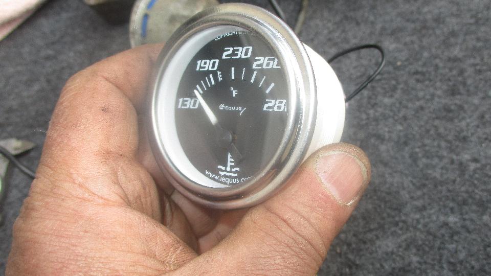
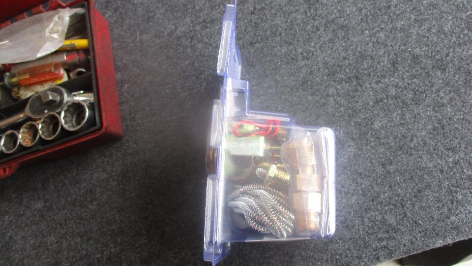
 There was a rather long delay while we were running about town gathering a few supplies. We made a few stops looking for a tiny #4-40 thread tap with no luck. But we did pick up some fasteners and an analog temperature gauge, cheapest one in the store, about $15. More on this later. 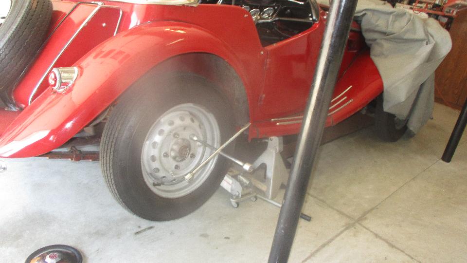
 Now about that new analog temperature gauge, .... This would be a second attempt to repair my nonfunctional safety gauge, wanting to know I could do it before we would attack Georges original safety gauge. My old gauge already had a small brass tube splice connector soldered on the original steel pipe, so we were half way there to begin with. I was a little worried about the new gauge being in a higher temperature range for newer cars (maybe the wrong fluid formula), but we would give it a try anyway. First move is to preheat a good strong soldering iron and be sure it has enough heat to heat the copper tube enough to melt solder in short order. 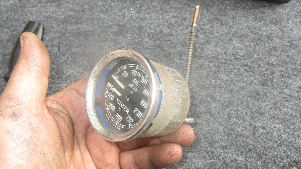
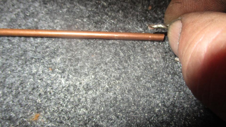
 The pipe on the new gauge was a tiny copper tube covered with a thick plastic sheath, very flexible and not the least bit prone to kinking. Functionally nice, but need to match the coupling bore to the new pipe OD. The coupling tube is 0.125 ID and 0.063 ID, drilled to 0.075 on one end to fit the original 0.070" steel pipe. Measured diameter of tubing on the new temperature gauge may be between 0.050-0.060-inch diameter (depending on source of the gauge), and it will most likely be a copper tube. Once the plastic tube was stripped back, this new pipe measured 0,047" OD, but I recon we can still solder it into the 0.063" ID coupling. 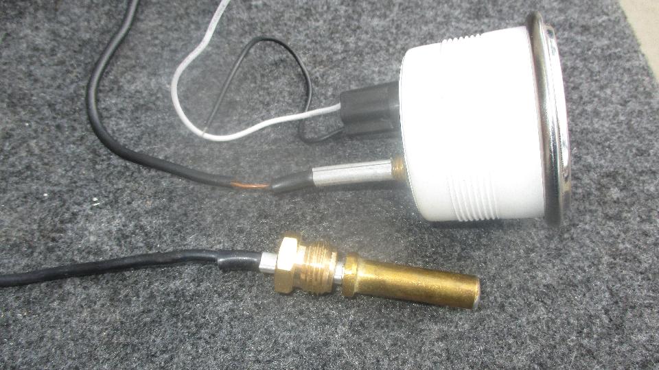
 After stripping the plastic cover from the pipe on the new gauge, we cut the tube close to the gauge using a Dremel tool with a thin abrasive cut-off wheel. Grind very slowly to prevent melting or munching the copper tube to close the hole inside. Check twice, and use a pick or needle to assure the tiny bore hole is open and clean. The new copper tube must also be clean enough to accept solder. For tinning the steel pipe on the original gauge, use acid core solder or solid solder and acid flux. Do not attempt to solder the coupling to the original pipe until you have successfully tinned the steel pipe. Once the steel pipe is tinned, then you can use resin core solder or solid solder and resin flux to solder the coupling to the pipe. Be sure not to plug the pipe with solder. Then use resin core solder or solid solder with resin flux for soldering the copper (or brass) coupling to the new copper pipe. 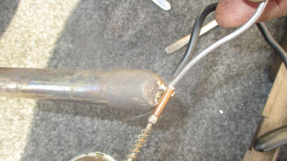
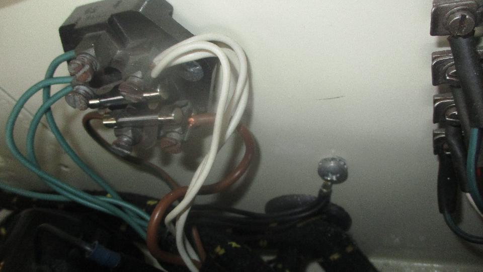
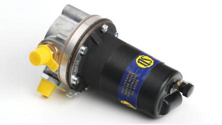
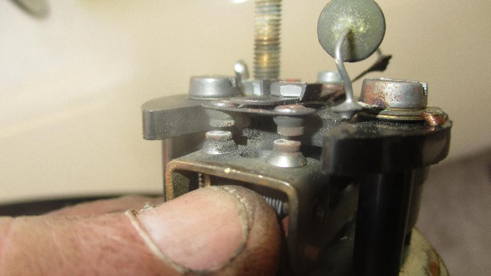
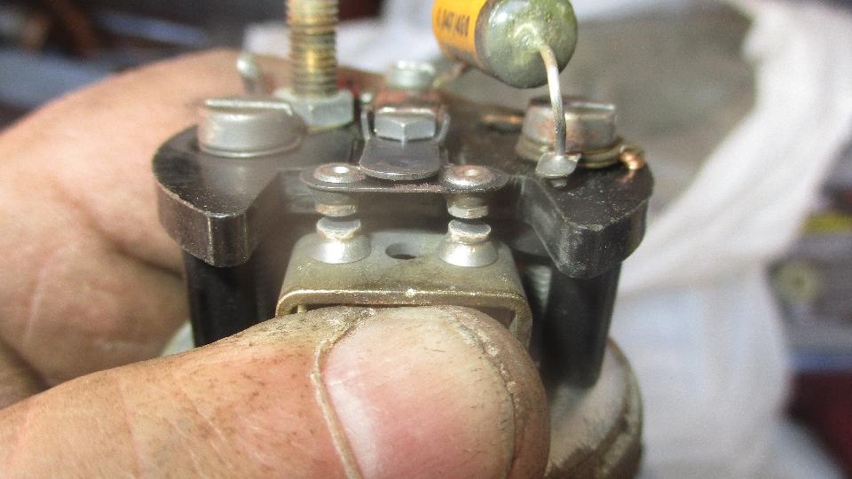
 Picture here is the original Lucas flasher unit with #6-32 female threads in extruded holes in the terminal posts to attach wiring harness ring lugs with screws. If that wasn't fiddly enough, the replacement (Chinese made) flasher 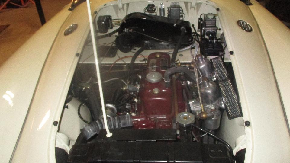
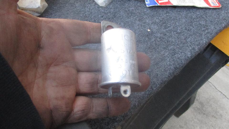 unit from Moss (with no markings on the can) has 1/4-inch Lucar push-on terminals with plain punched holes, no threads. To use the original screws you would have to tap #6-32 threads in the terminal blades (which are rather thin). Otherwise, Moss has supplied smaller #4-40 screws with hex nuts (even more fiddly).
I did manage to assemble the tiny screws and nuts, and we soon had the flasher unit screwed to the firewall. We then swapped two wires on the turn signal switch to get the flashers working in the correct directions.
unit from Moss (with no markings on the can) has 1/4-inch Lucar push-on terminals with plain punched holes, no threads. To use the original screws you would have to tap #6-32 threads in the terminal blades (which are rather thin). Otherwise, Moss has supplied smaller #4-40 screws with hex nuts (even more fiddly).
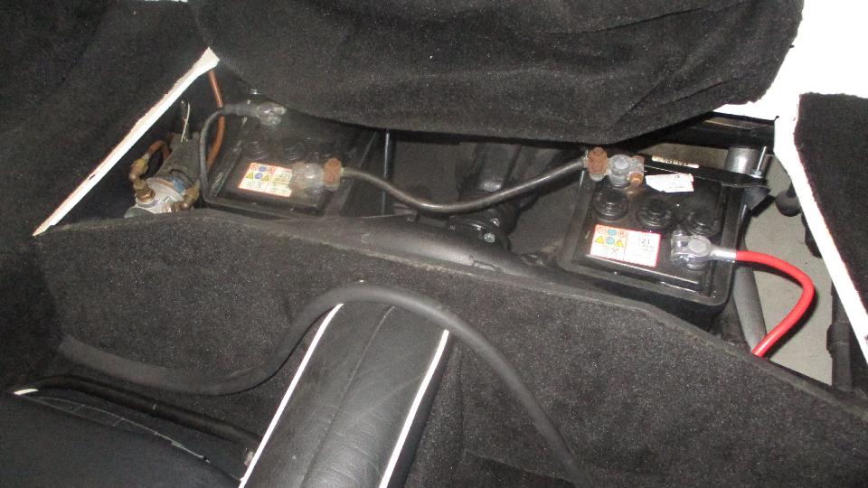
I did manage to assemble the tiny screws and nuts, and we soon had the flasher unit screwed to the firewall. We then swapped two wires on the turn signal switch to get the flashers working in the correct directions. 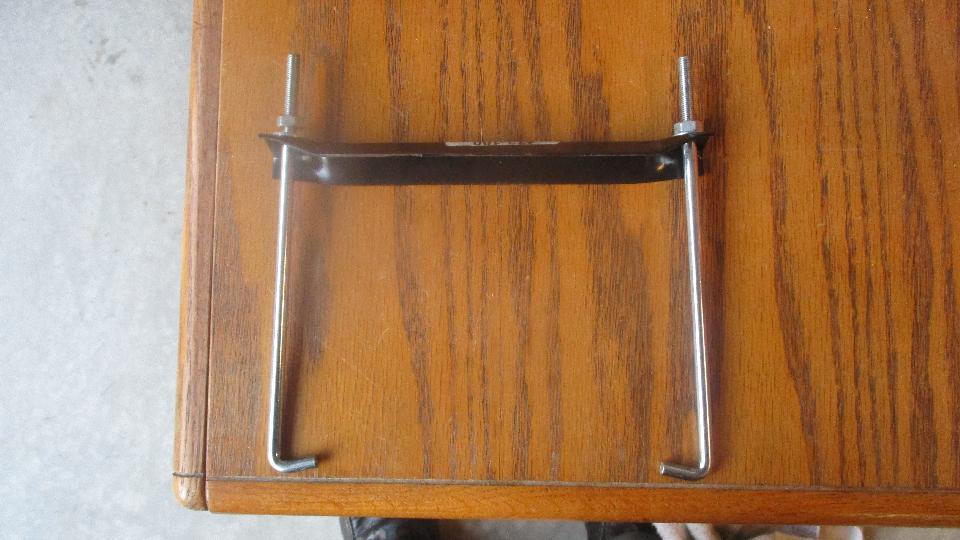 the nuts down tight. So it was off to the magic trailer to retrieve a 1/4-28-UNF threading die and handle to put another 15 to 18 turns on the threads. After that it was just a little fiddling to install the bolts and clamp bars with the proper thin plastic pad strips under the bars, and soon the batteries were secure and solid as a rock. Note that the original J-bolts were shorter inboard and longer outboard, so it would be appropriate to cut off the extra length on the inboard bolts.
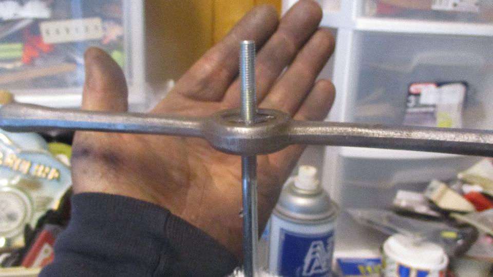
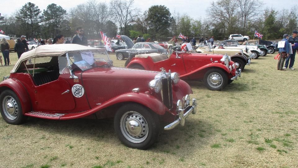
 Time to call it a day, as George will be busy and we have other things to do on the week end. Saturday March 24, 2018: Tucked into the middle of a busy schedule we managed to attend The Carolina British Classic car show presented by British Car Club Midlands Centre in conjunction with The Highland Games at Columbia Speedway in Cayce, South Carolina. About 136 cars on display today. 

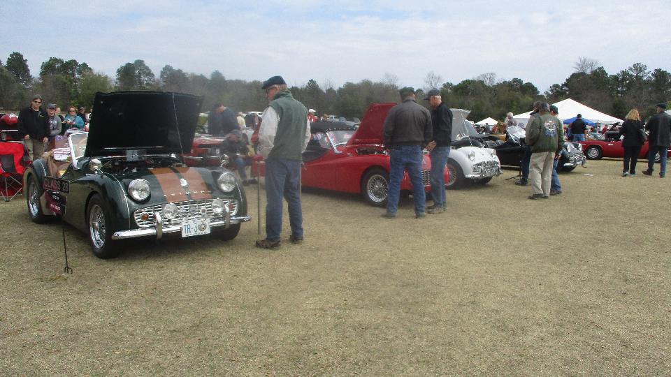
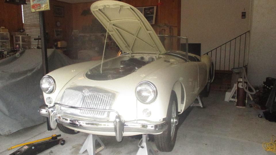
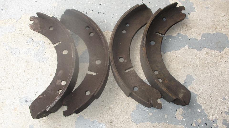
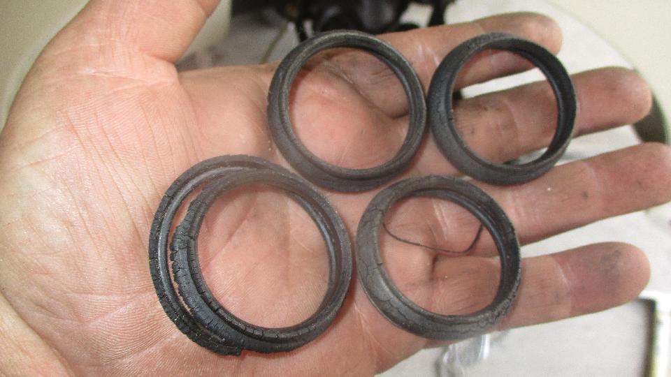
 Check here for more than 50 additioal photos and notes from the car show: carolina_bc.htm. Sunday March 25, 2018: Maintenance day for my MGA, with the generous loan of garage work space from Dave Daniel in Lexington, SC. First up was to change out the rear brake shoes, which in itself is straight forward and just a little (dirty) grunt work. The only problem here is that new brake shoes I have been buying form Moss Motors (for the past few years) are too small, so the brake adjusters run up all 18 notches to end of adjustment range when the shoes are new, and the shoes still do not quite touch the drums. When the shoes become about 30% worn we have long pedal travel, and the parking brake stops working entirely. Since there is no more adjustment range, the nearly new brake shoes have to be tossed out and replaced. We are going to have to find a better source for brake shoes (like the local NAPA store maybe). 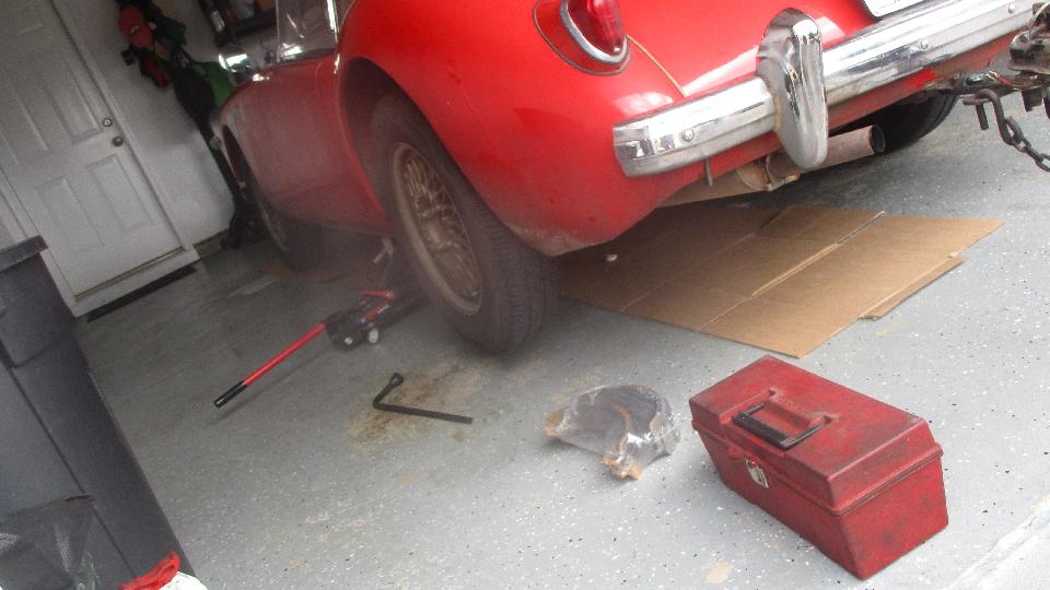
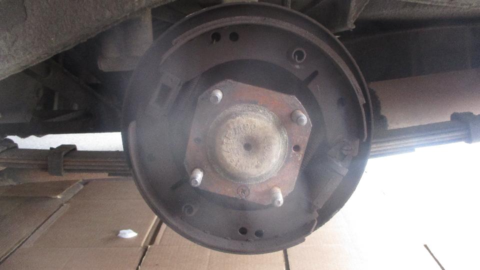
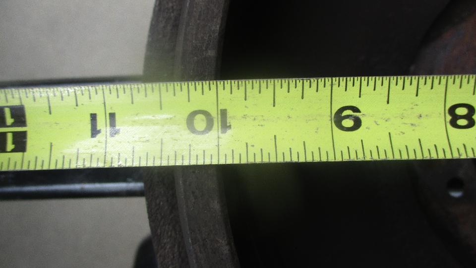
 To be sure, this is not a matter of oversize brake drums, as these are fairly new drums (also sourced form Moss Motors) that have never been turned and are still at 10-inches diameter as original. See picture of the brake shoes with very little wear that have been removed as non-functional. Front brakes with two adjusters are a bit more tolerant of the undersized shoes. Installed 18 months ago, and having about the same wear the 30 month old rear shoes, these are now on the last click of adjustment and will have to be replaced next time they need adjustment. Bummer. This problem has been around quite a long time. I had notified Moss Motors about this problem (again) two years ago, but they are still selling the same bad parts now. What else can I say except to advise people not to buy these parts from Moss Motors? 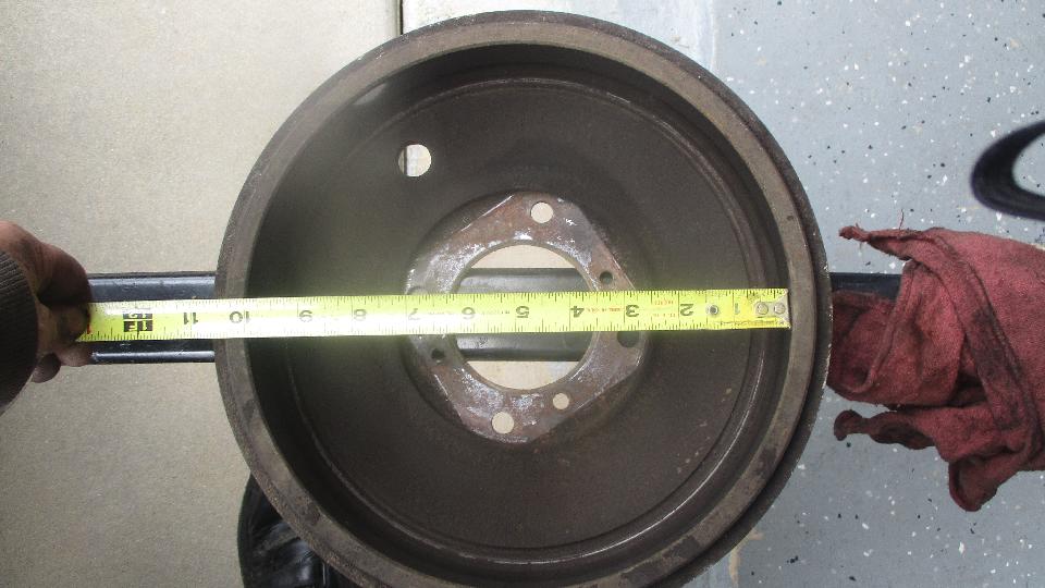
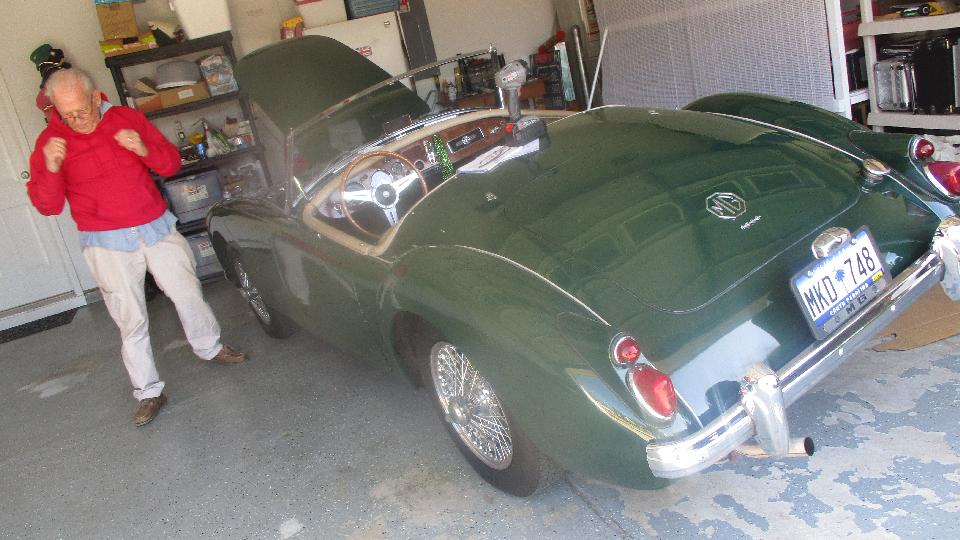
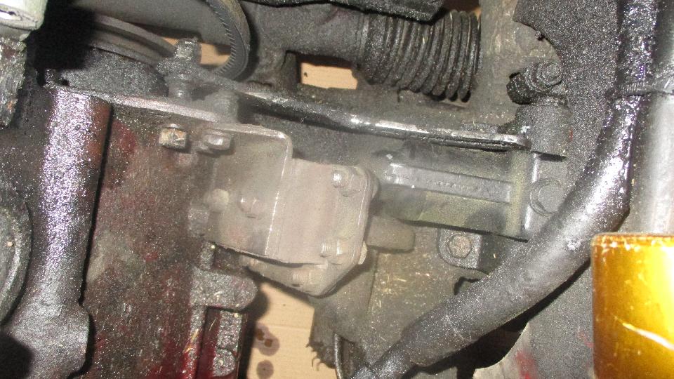
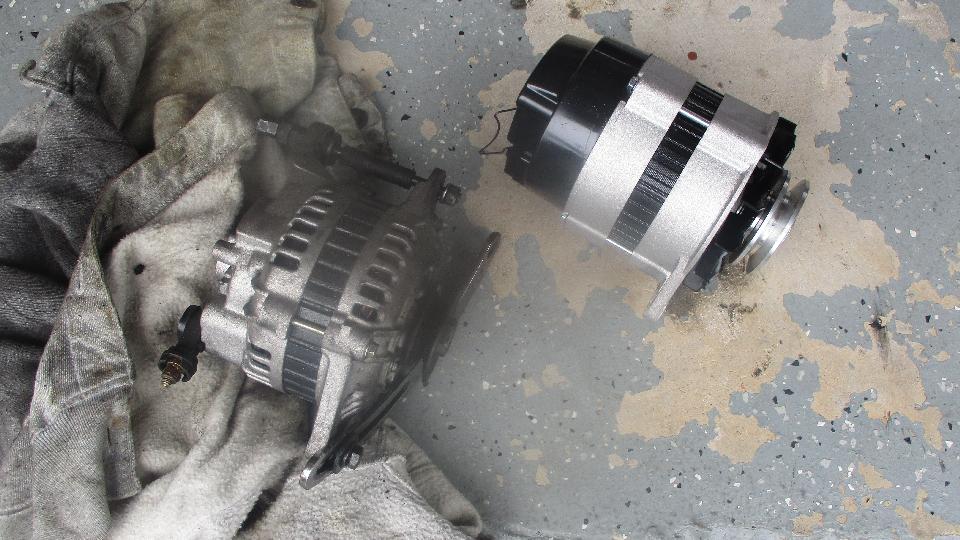
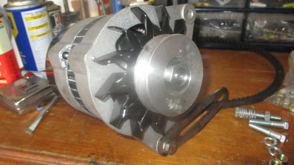
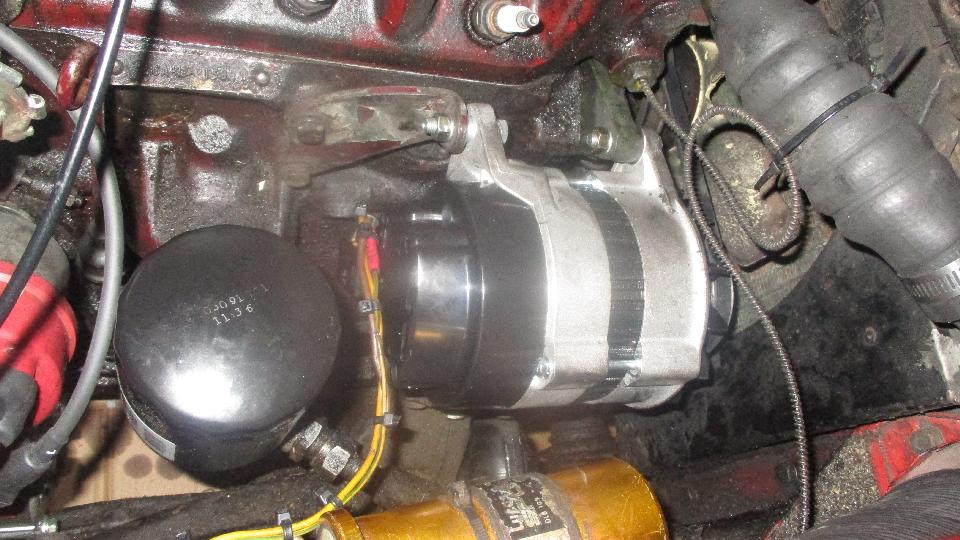
 The other important job for the day was to replace my somewhat troublesome jury rigged Mitsubishi alternator with a more standard Lucas alternator (which is a normal retrofit or conversion part for MGA). Disconnect battery ground, disconnect alternator wires, unbolt and remove old alternator. Notice the non-standard speed shop J-bracket still attached to the original adjuster pedestal, which was relocated to a new hole drilled one inch below the original hole in the front plate. Unbolt the rogue adjuster arm, and relocate the pedestal back into the original hole. There is the old Mitsubishi alternator with all related mounting parts lying beside the new Lucas alternator with fan and belt pulley already attached. 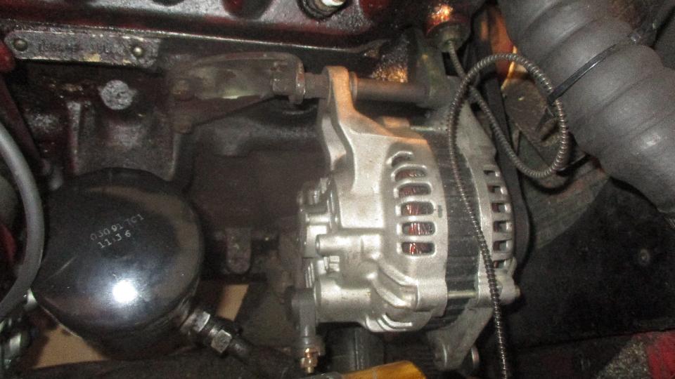
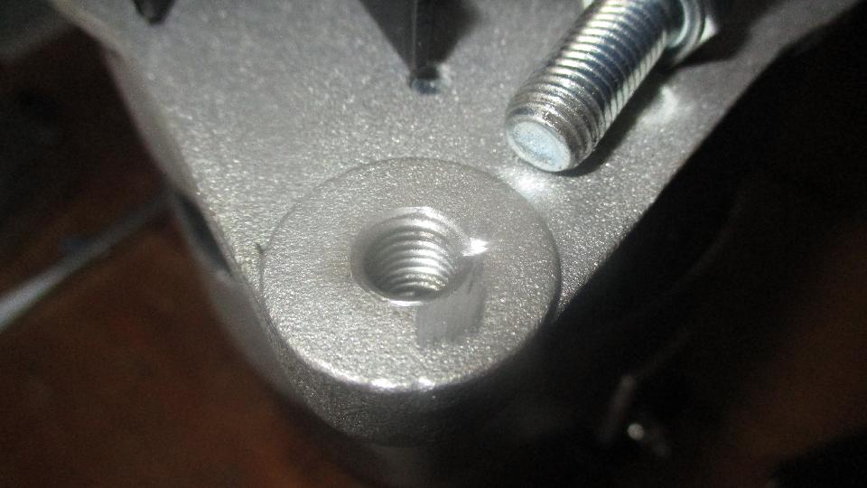
 The next issue was that many Lucas parts may now be made in China (good bet). In any case, the new alternator has a non-standard metric thread in the hole for the adjusting bolt. Since I do not want to carry an additional full set of metric tools in my traveling tool kit, I will not tolerate this. 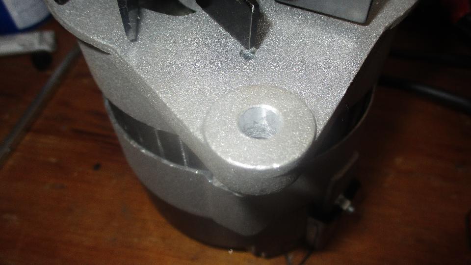
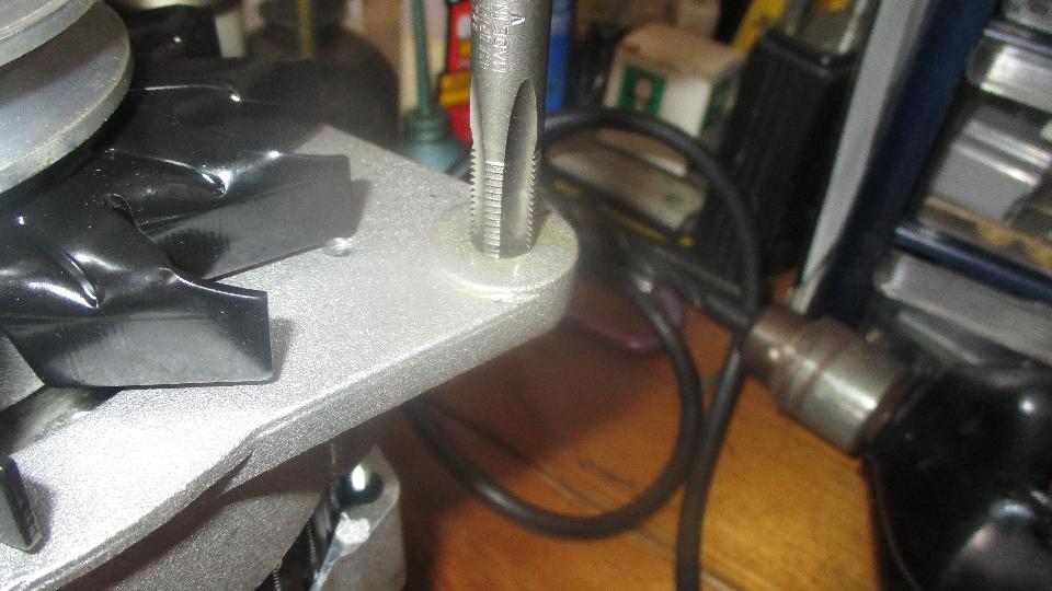
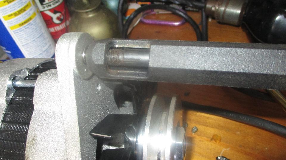 So drill out the threads, tap the hole and install a nice stainless steel Heli-Coil to restore a proper 5/16-24-UNF thread, break off the insertion driving tab, install a new bolt, and it's ready to install in the car. 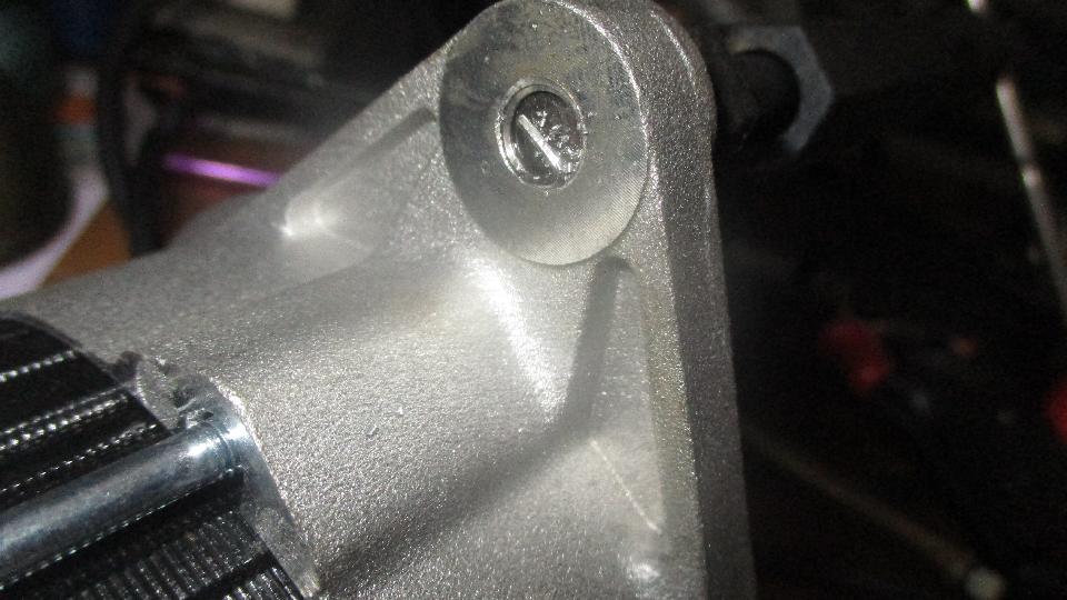
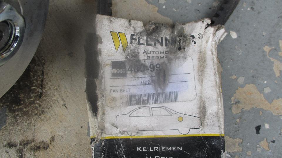
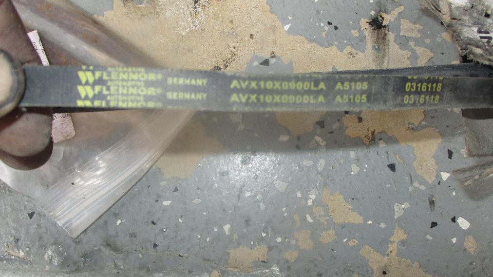
 Then another minor problem (nothing is easy), the new fan belt is too short and cannot be installed. Last summer I was in the Moss Motors facility in Golita, California picking up some parts (including the new adjuster bracket). The fan belt for the MGA Lucas alternator conversion is not listed separately, so I requested a V-belt as a replacement part specifically for the MGA alternator conversion, and this is what they sold me. It is their part number 460-990, which on review is the belt for the standard MGA generator setup. Bummer. So I still do not have a Moss part number for the belt for an alternator on the MGA. At least I can keep this one as a spare part for a standard generator MGA. 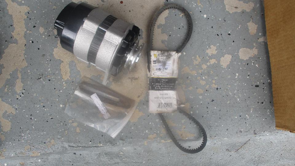
 By very fortunate coincidence, I happened to have a spare V-belt for the old Mitsubishi alternator, and it happens to be exactly the right length for the Lucas alternator conversion. It just slips over the pulley in the minimal adjustment position, and it pulls up tight right in the middle of the adjustment range with the new belt, plenty of range for adjustment as the belt may wear. It is NAPA Premium XL, number 25-7365, 0.41-inch wide x 36-1/2-inch long. NAPA number 25-7370 being 1/2-inch longer would work as well. 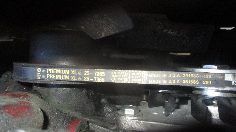
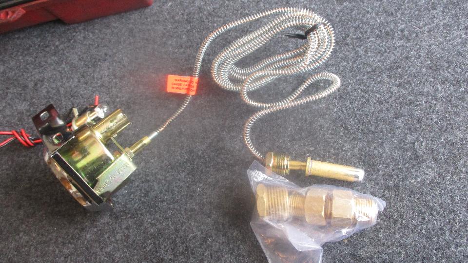
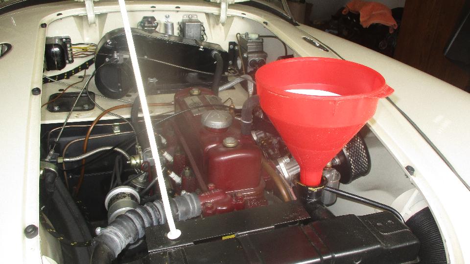
Monday March 26, 2018: This was destined to be a rather fun half day back at George's place. Having succeeded in restoring function of my slightly ratty temperature gauge last Friday, we were about to do a little better job of fixing the nice one in George's MGA. This starts with a $17 Bosch analog temperature gauge procured from the local Advance Auto parts store. I paid a few bucks extra for this one because it has the spiral wrap spring wire around the small pipe very similar to the original unit in the vintage car, good for appearance sake, and maybe a little better protected. It also comes with male pipe thread adapters in three different pipe sizes so it could be used for water or oil temperature sensing in any application where a female a pipe threaded port is installed. 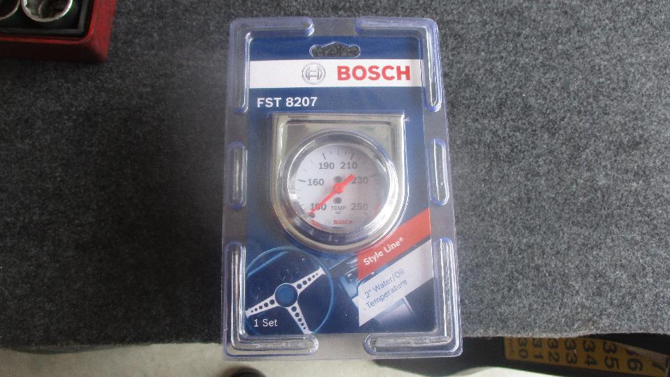
 To remove the dysfunctional gauge from the car, start by draining the coolant and unscrewing the sensor bulb from the cylinder head. Detach any securing clips, and snake the sensor tube back through the firewall. Detach an illumination lamp and a ground wire from back of the gauge. Remove the securing bracket from behind, pull the gauge out of the dash, disconnect the oil pressure signal pipe, and snake the temperature signal pipe out through the dash aperture. 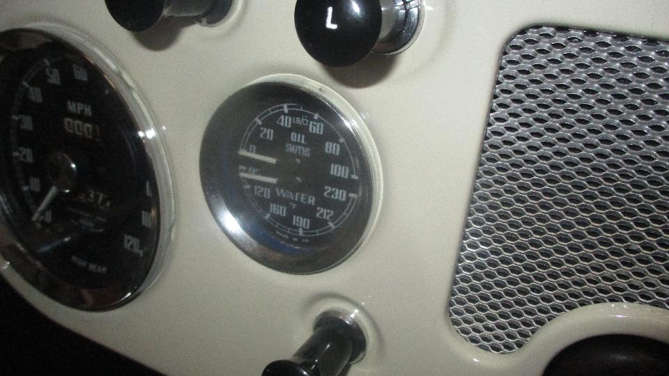
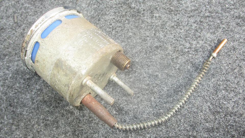
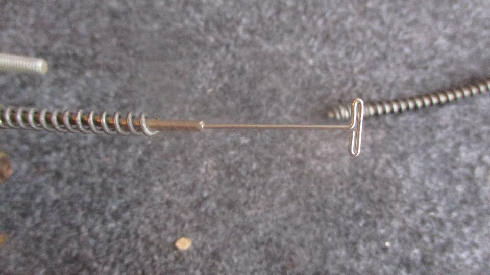
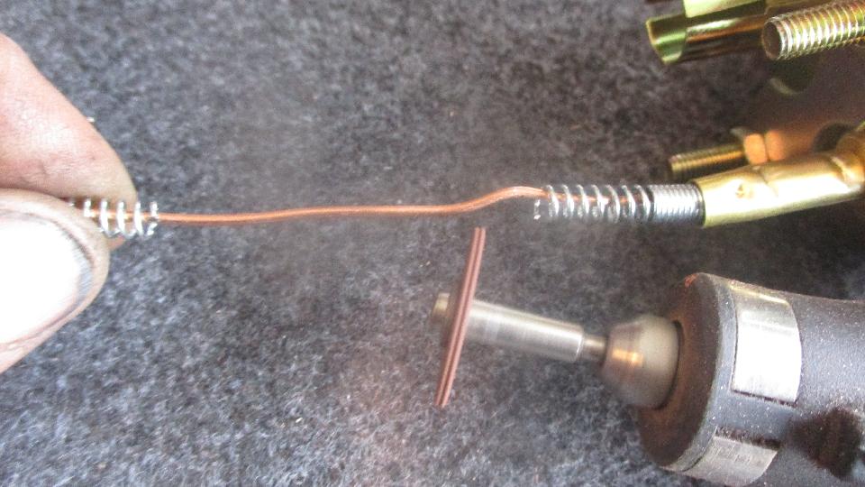
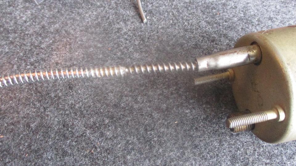
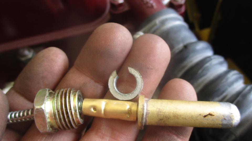
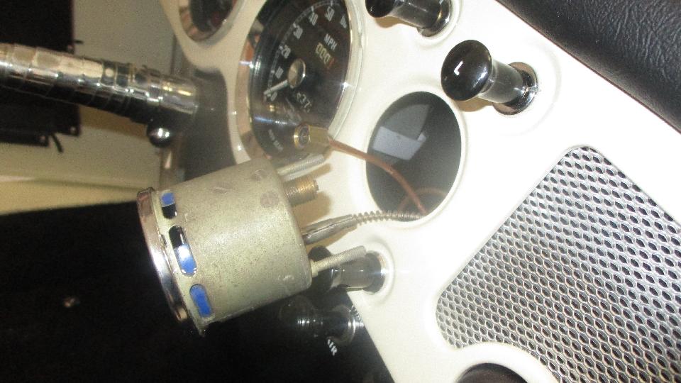 Not knowing where the original leak occurred that disabled the gauge, we will be replacing the full length of signal pipe right up near the back of the gauge, but leaving a short stub to work with. Maybe on some future attempt I may try joining the new pipe inside the gauge, but not this time. I begin by cutting through the protecting spring wire in two places a half inch apart, then screw the loose piece of spring down into the remaining coil for open access to the pipe. Then cut off the pipe leaving about 3/8-inch of bare pipe exposed. 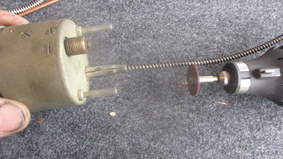
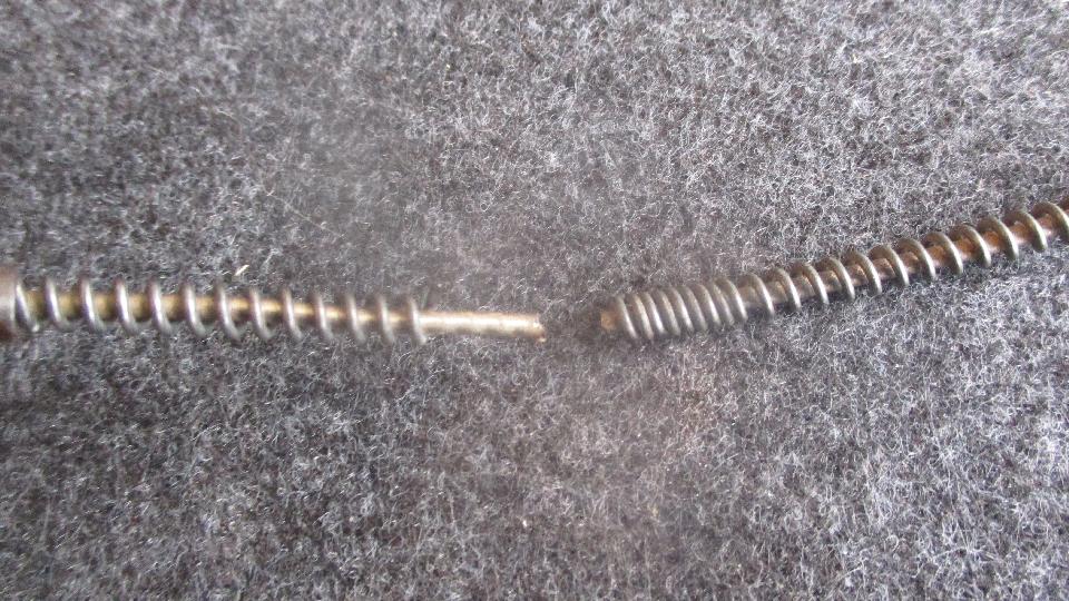 We use a stick pin to clean the bore end of the remaining stub pipe on the gauge to assure there is no flow obstruction. You could suck on the pipe and put your tongue over the end to assure it will flow an will hold a bit of vacuum (no leak allowed). 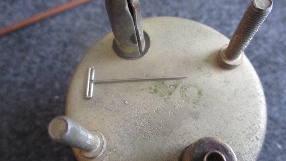
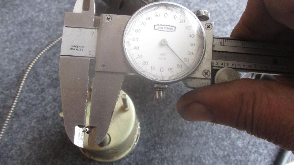 Measuring the old pipe was actually done before ordering the tubing that will be used for the coupling. The old pipe size is 0.074-inch diameter. Clean any corrosion off of the vintage pipe to make for easy soldering.
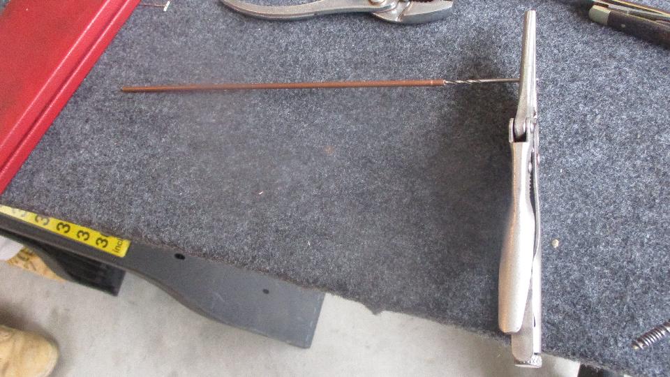
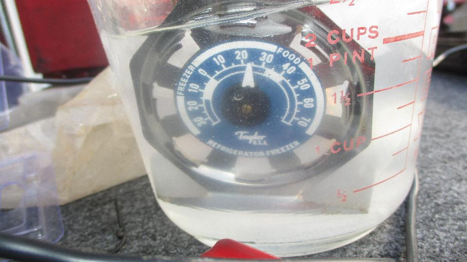
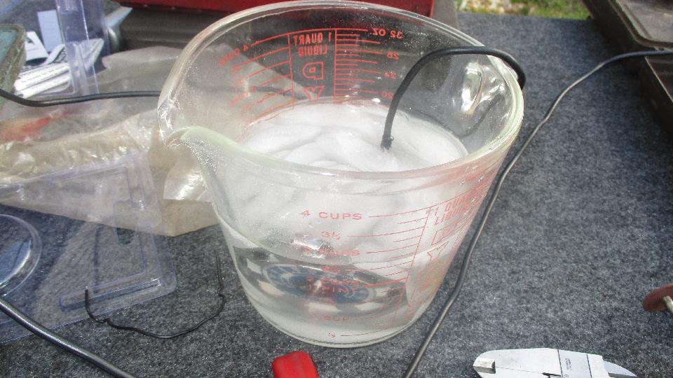
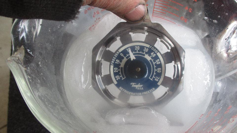
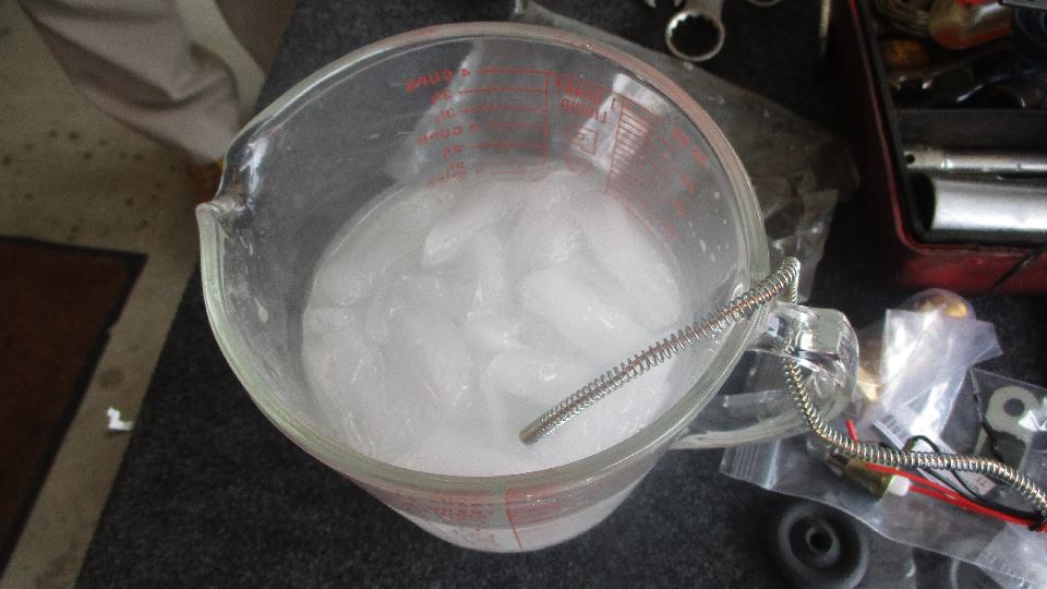
 Zeroing in on the real fun, we need some iced brine water. A few days earlier we succeeded with minimal salt in the water, and 24dF cold water. Makes me wonder if this operation might work at 32dF (but not going to try it now). This time we have plenty of salt handy, so just keep adding salt until some of it settles out when no more can be absorbed into the water. The iced brine water is then 10dF, so this is going to be easy. In theory, saturated brine solution should reach -6dF (-21dC), so maybe the cheap refrigerator thermometer is reading up to 16dF too high (which would mean the last one was done at 8dF rather than 24dF). Or more likely we didn't wait long enough for total saturation. Saturation occurs with about 3 ounces of salt in one cup of water (if you stir it long enough). Knowing what the mixture is, if you use enough salt and ice you don't need the thermometer. Stick the new temperature gauge thermal bulb in the iced brine water to soak, and be sure it will stay there for the duration of the next operation. 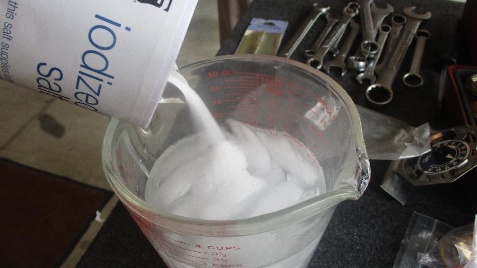
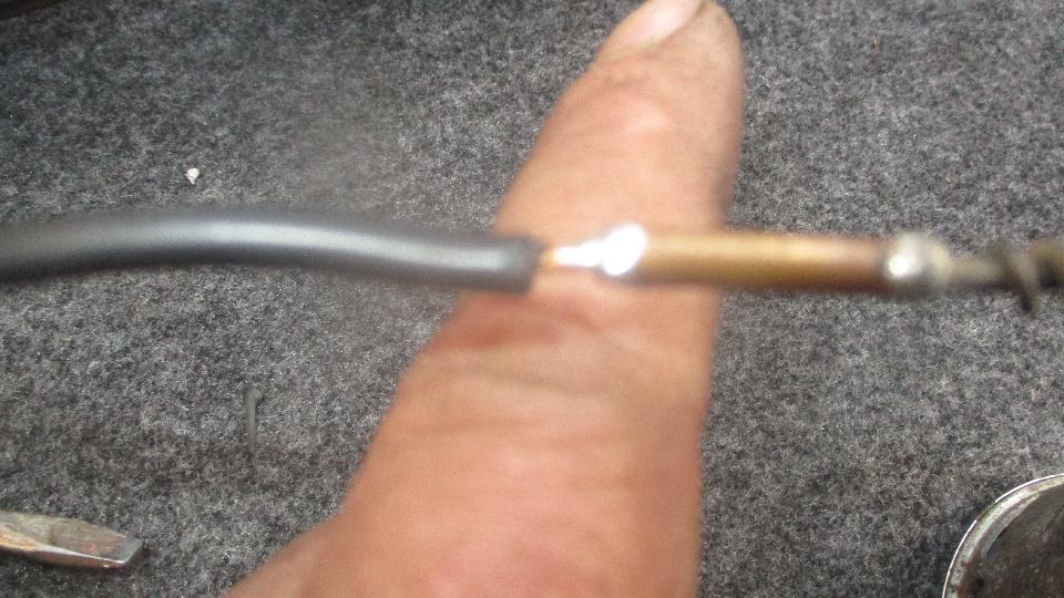
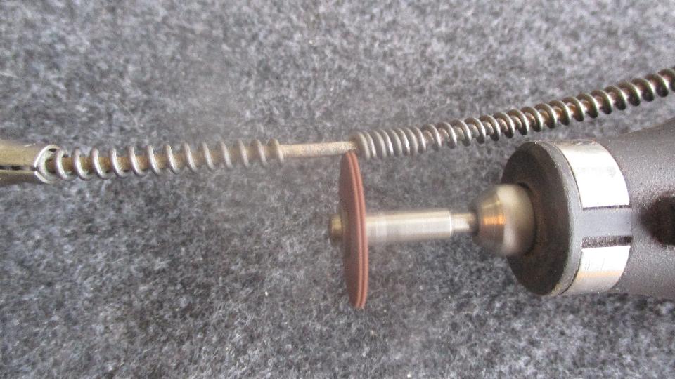
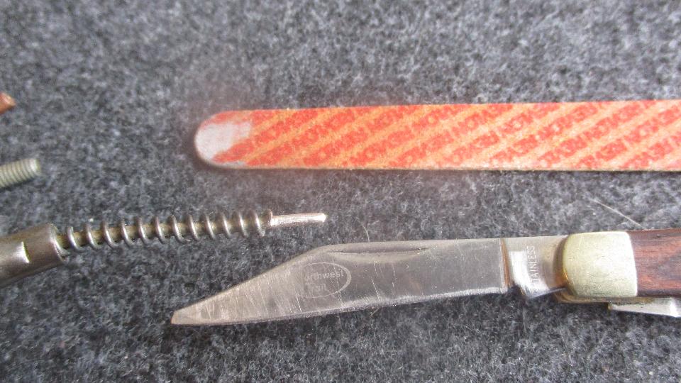
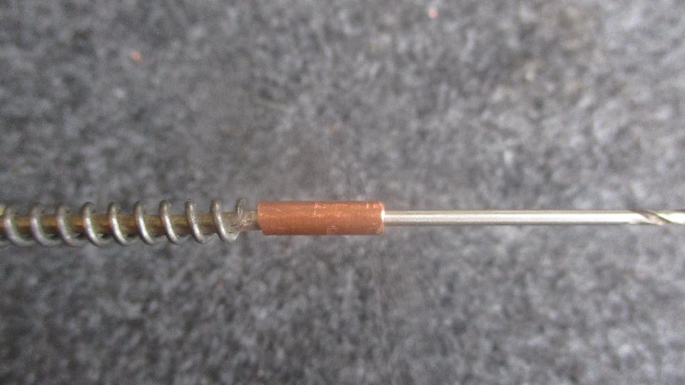
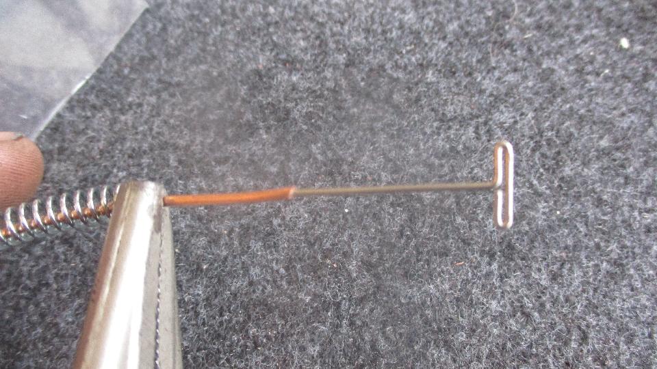
 The tube on the new gauge should also be measured. Most of the new ones will be in the range of 0.060" down to 0.045", just be sure it will fit inside the 0.063" bore of the coupling tube. If you are sharp you may have the rubber bulkhead grommet handy to slip over the tube when it is cut and before it is re-joined (because the grommet will not fit over the thermal bulb and flare nut). We cut the spring wire only once near the new gauge, then pulled the spring down the tube a bit and clamped it there with a small locking pliers. Then cut the tube near the gauge. Again, use the stick pin to clear the bore in the cut end of the tube. 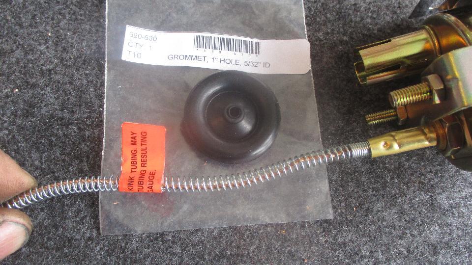
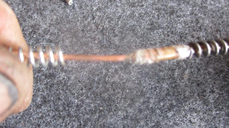
 Now we were to be soldering a copper tube into a brass coupling, so we used resin core solder (same as for soldering copper wire). All of the copper and brass bits were new and clean, so this joint was quick and easy. Once the pipe was soldered in place (hermetically sealed of course), we gave the new spring wire a few turns of counter twist, then slipped it over the coupling tube with a little forward twist. This was a nice snug fit so the spring held well on the coupling tube. The larger steel pipe is significantly stronger then the new copper tube, to the new pipe can wank around a lot while the steel pipe hardly wiggles at all (seems almost solid by comparison). If you wanted to assure that the spring would stay put, you might consider adding a bit of heat shrink tubing over the spring before final soldering. 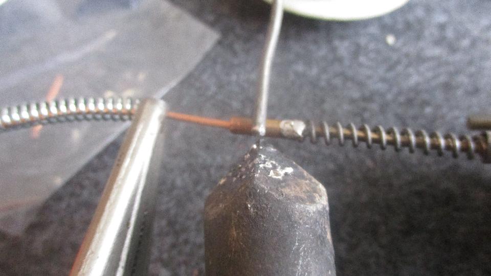
 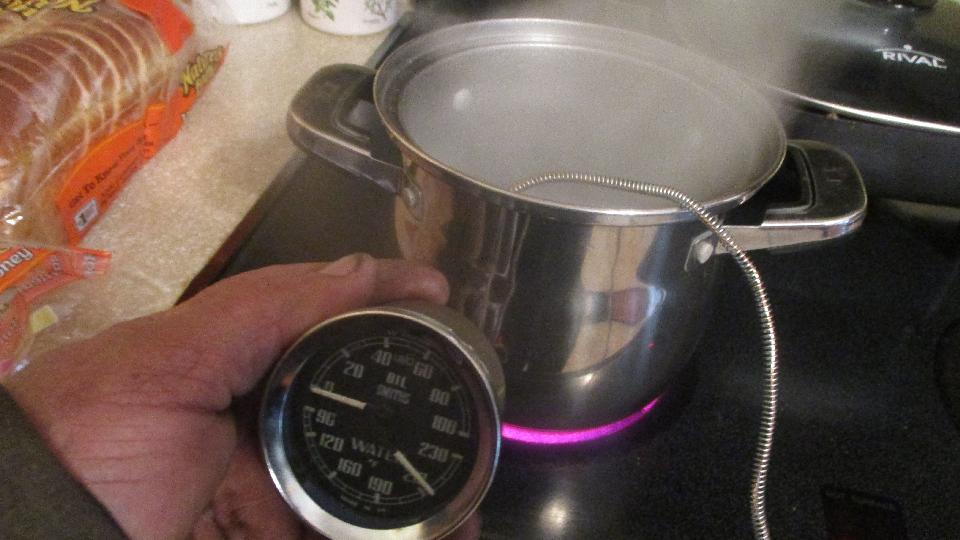
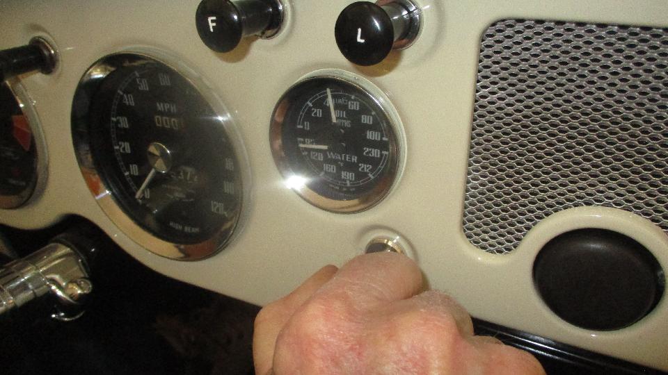
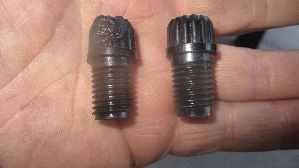
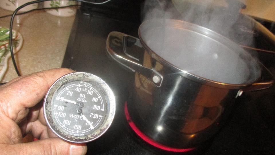
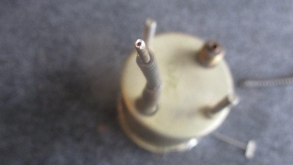
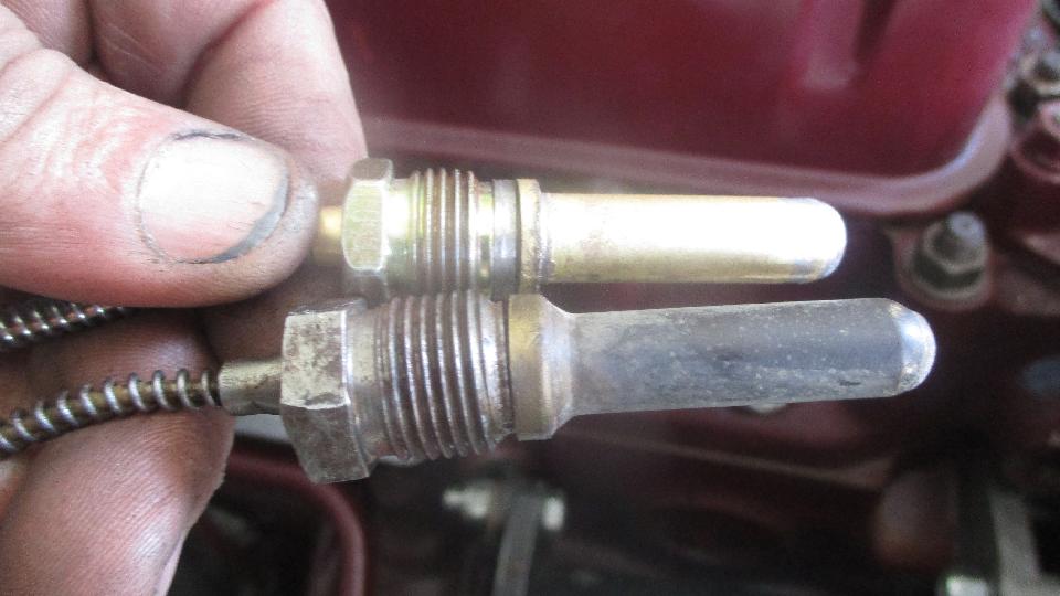
 Then a quick trip to the kitchen to boil some water, and the nice vintage temperature gauge was reading spot on 212dF. The piece on the right is the remains of the new gauge that we get to toss in the dust bin.
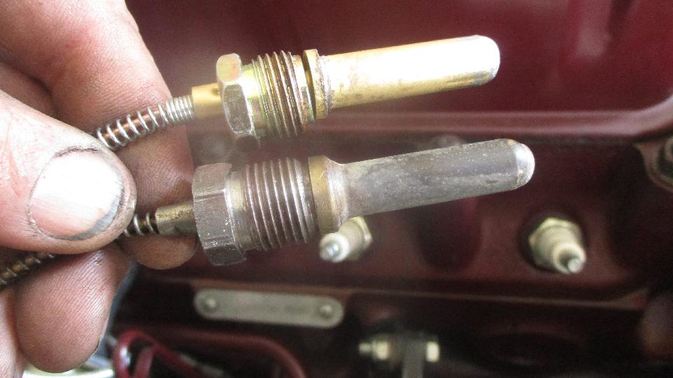
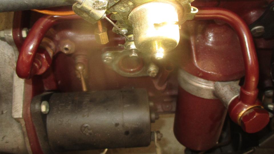
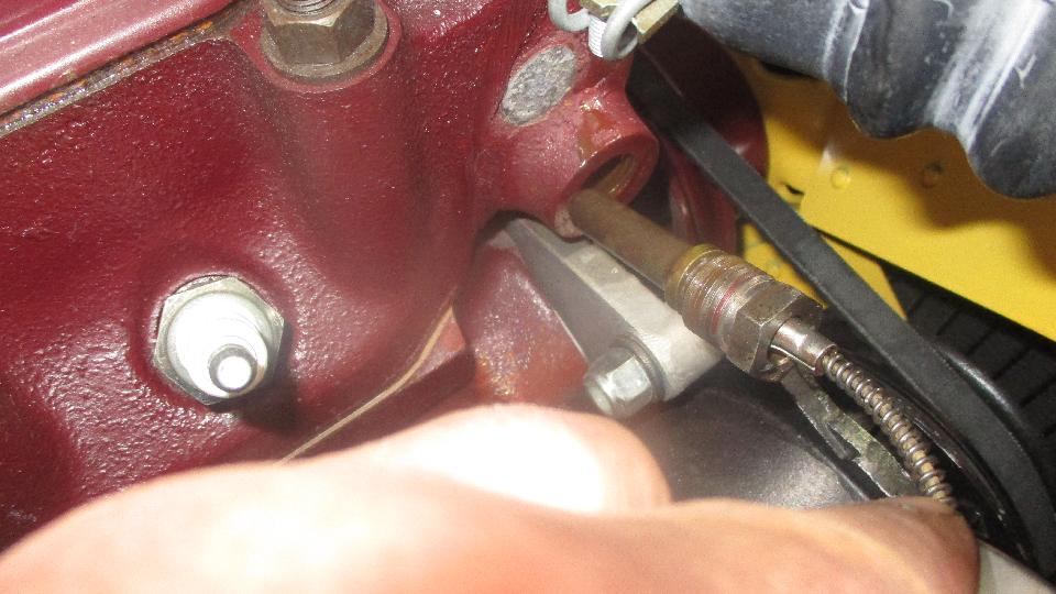
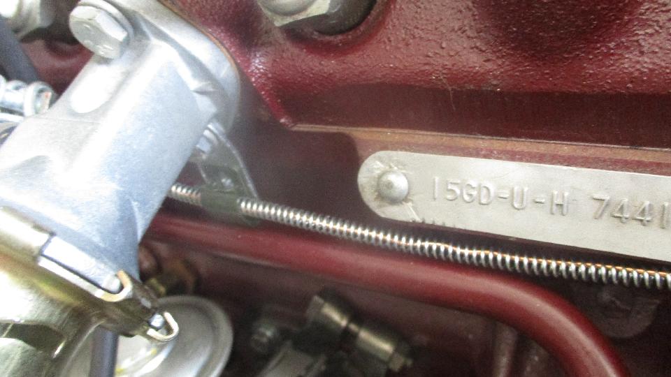
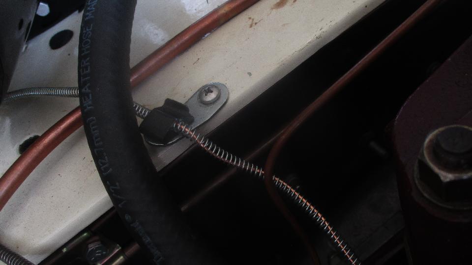
 Sensor in place, center clip under the heater valve, another strain relief clip on the heater shelf. 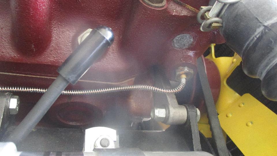
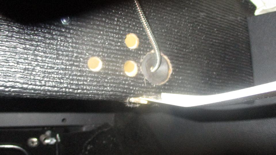
 New rubber grommet installed in the firewall, and the gauge being installed in the dash with a new dash seating O-ring. There is a small leather washer originally prescribed to seal the oil pressure pipe to the gauge, but most of the time this joint will seal up okay without the leather washer. Just don't crush the thin wall flare nut by over tightening. You can disconnect this joint, hold the pipe end in a catch vessel, run the engine until all air is bled from the pipe and oil comes out, then reconnect the pipe to the gauge. Removing air from the pipe will improve response time of the oil pressure gauge. 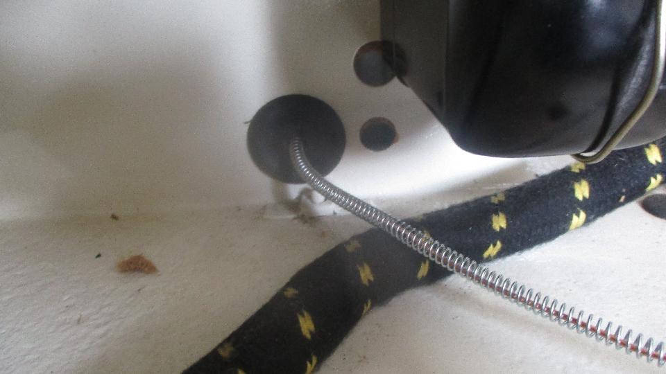
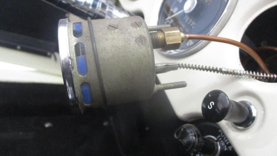 With the safety gauge installed we topped up the coolant, fired it up, tightened one lower radiator hose clamp to stifle a small leak.
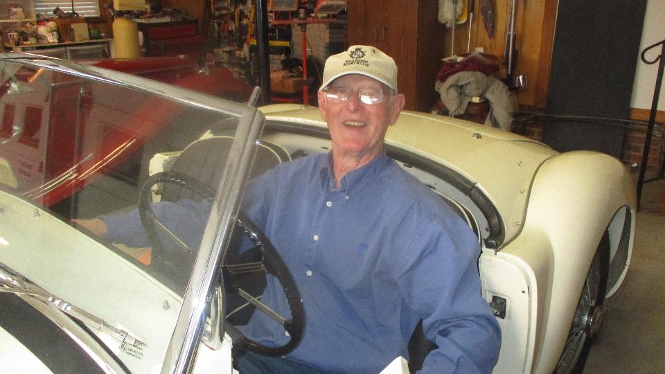
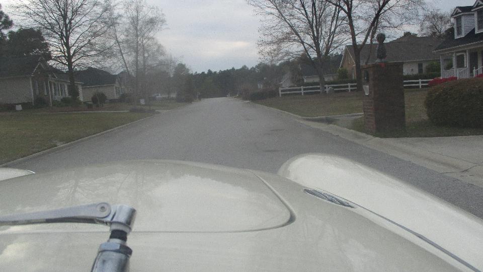
 Oh yeah, install a good used Lucas dipper switch while we are thinking about it, then time for a little pleasure drive. Nice that everything mechanical on the car works, and George has that wonderful ear to ear grin. 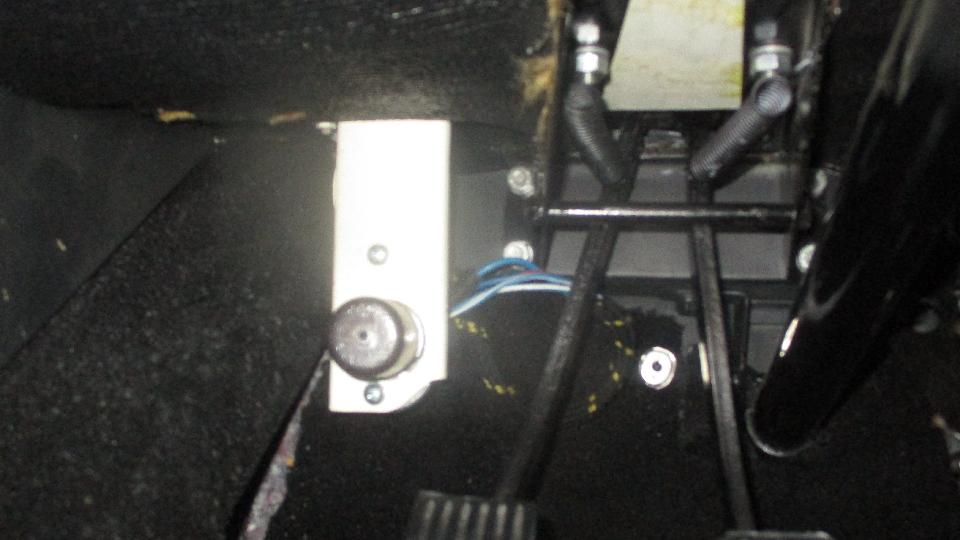
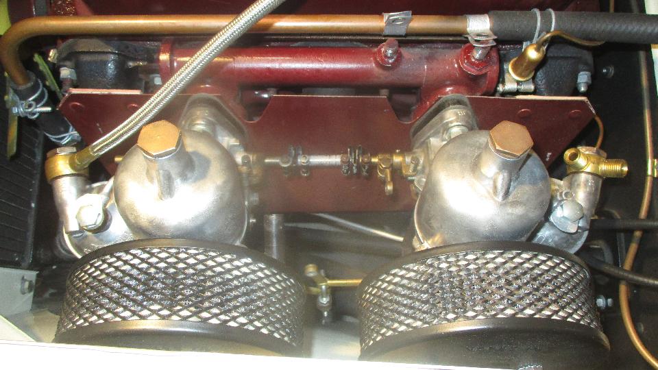
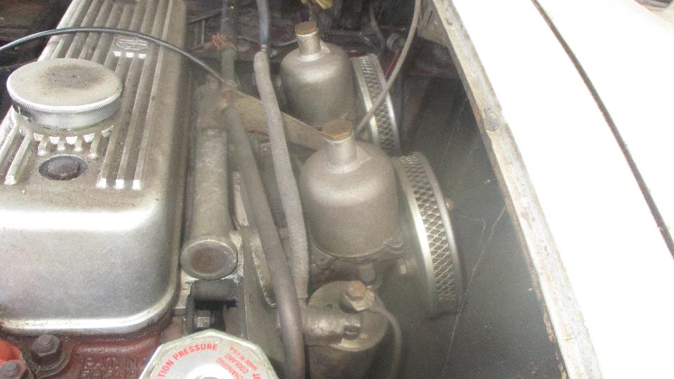
 Tuesday March 27, 2018: Back at George's place again. Seems like he is always happy to see me. Today we were going to fix a drippy carburetor problem. Not long to remove the carbs from the car and begin disassembly. 
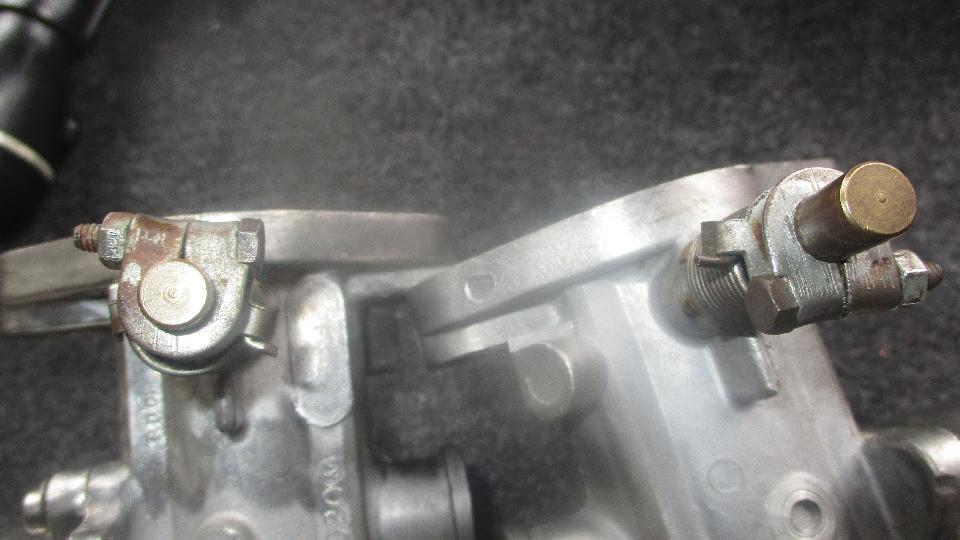
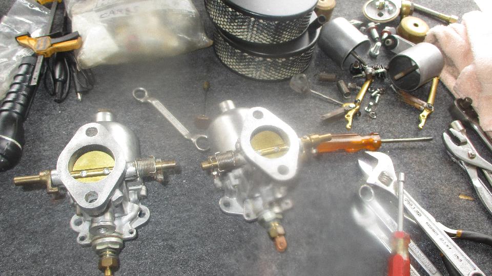 First notice was the throttle return springs were switched left for right, so they were wound the wrong direction, and loose. Trying to wind them tighter resulted int eh ends slipping over the mating parts, going round and round but never getting tighter. Didn't take long to swap the laft handed and right handed springs ad get them wound up the right way so the throttle shafts will snap home smartly.
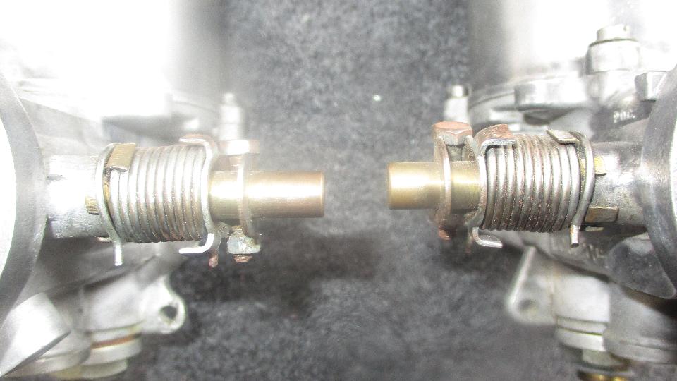
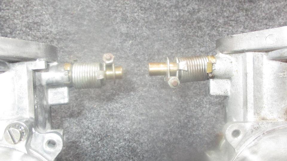
 Then we quickly discovered why one carburetor was leaking. The gland nut at the bottom of the main jet was loose on both carbs so the upper and lower jet bearings were not secure, the lower jet bearing would turn so the mixture nut could not be adjusted, and one assembly was so loose that fuel was dribbling out at the big cork gasket. It never ceases to amaze me how some pro shops can scew things up. 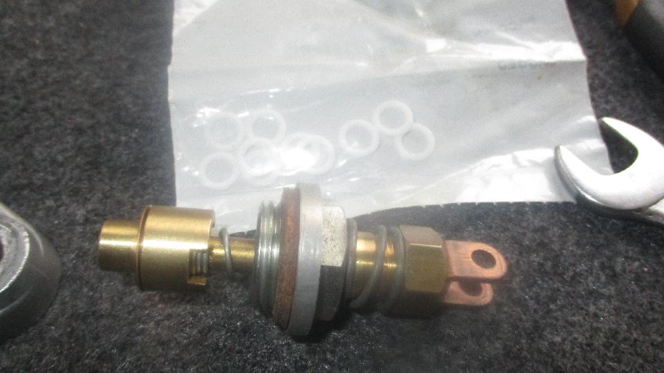
 Since the choke cable was previously super slack (generally non-functional), the DPM had the fast idle cam link in the third hole of the cam (not enough compensate for the cable error). After setting that right and getting all of the links reassembled, not long to get the carbs back in the car and linkages properly adjusted. It was soon running like an MG again, no drips, happy engine. 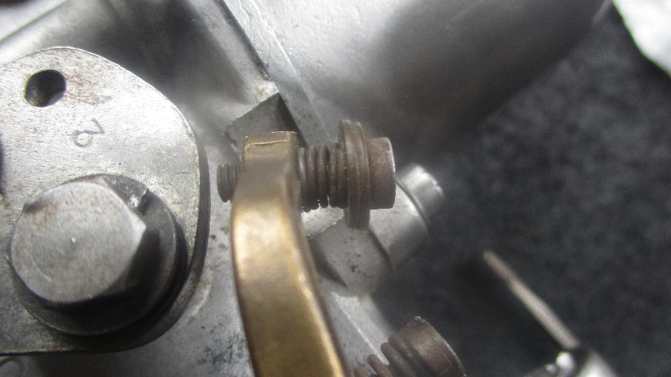
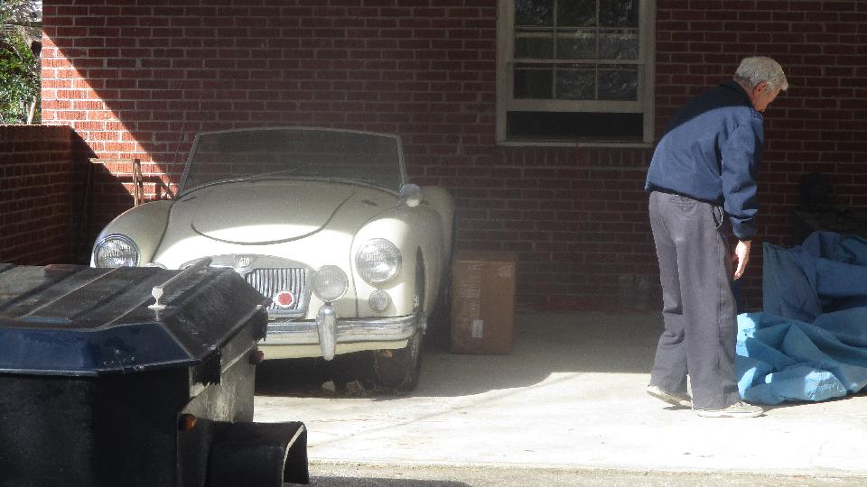
 By late afternoon we were headed half hour away to downtown Columbia, SC to check out an MGA 1600 owned by Ansel Gantt. Story is, it was last driven five years ago, then parked. Two years ago some mechanics picked it up intending to get it running again, but brought it back with bad news. They said the engine was seized, that four burly guys were pushing it back and forth vigorously in 4th gear but could not get the engine to turn. My intent today was to check it out in person to see if it might be saved, or if it may need an engine rebuild or an engine transplant. So first we stuck it in 4th gear and gave it a shove, and the engine turned. Really? Go figure. Your guess may be as good as mine, but at least we would be able to make it run without pulling the engine out. 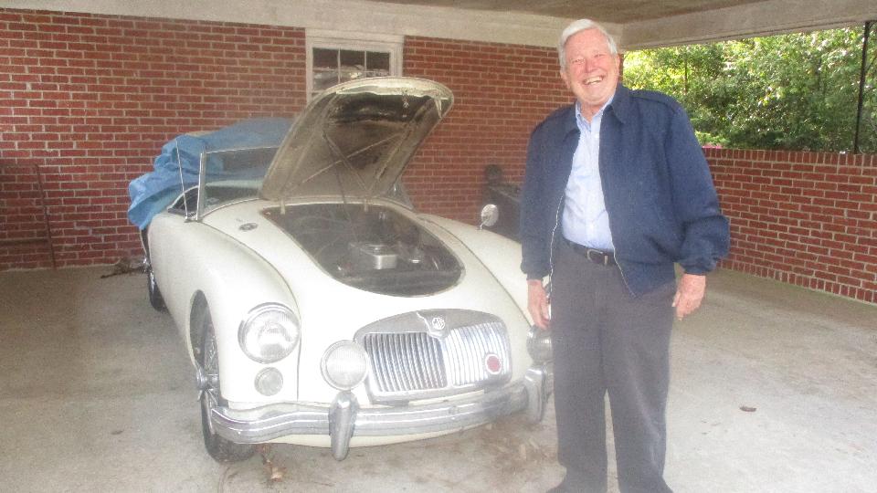
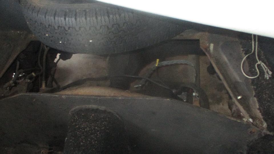
 So we set about investigating what was required to get it running. Begin with a new fuel tank and related mounting hardware, a fuel lever sender unit, a new pipe from tank to fuel pump, fuel filler connector hose, and hoping to get the fuel pump to work. If not, I have an aftermarket fuel pump on hand in a pinch. 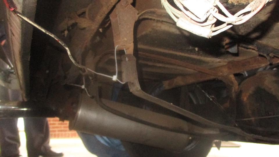
 It will need a new battery and a battery, hold down clamp parts, and a battery ground cable. I have parts to rebuild the carburetors (likely necessary). Having taken a bunch of pictures, I will spend time this evening making a parts list to order tomorrow, expecting the stuff to arrive Friday. 
 Wednesday March 28, 2018: Got most of Ansel's parts listed last night, finishing up review and a few minor additions this morning, and email the list to Ansel to get the stuff ordered today, expecting to have delivery by Friday. 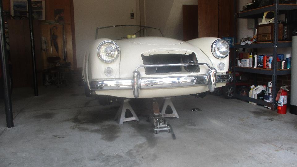
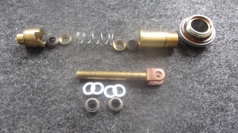
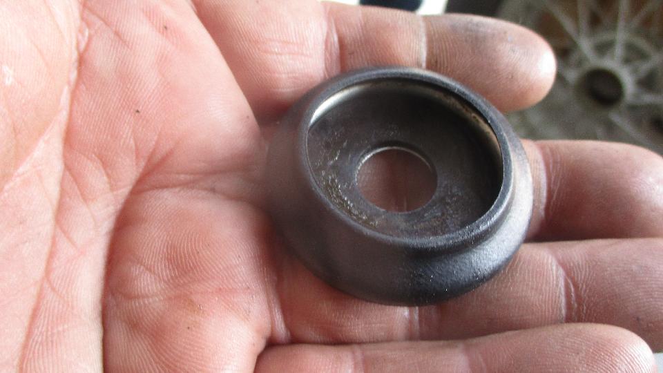
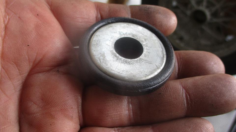
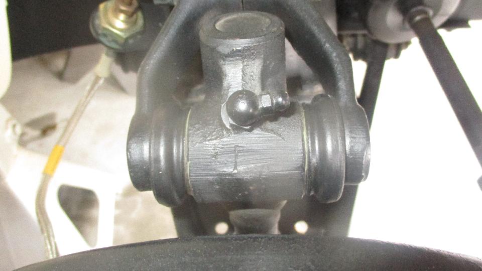
 This is how the new parts go together. Seal carrier cup side up, thrust washer inside the cup, and then the seal snaps on over it all. Flip side over, back of the seal is flush with back of the carrier. 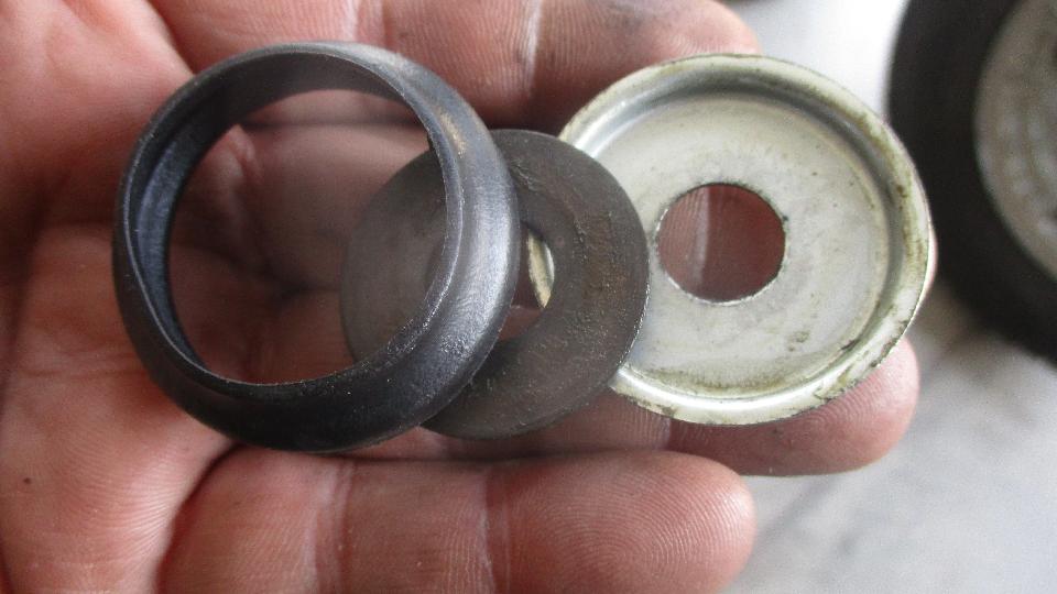
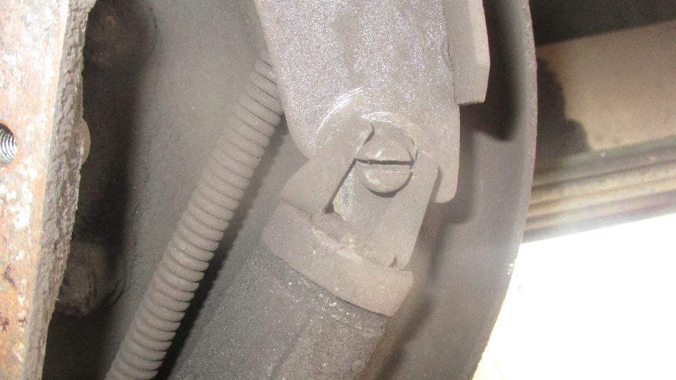
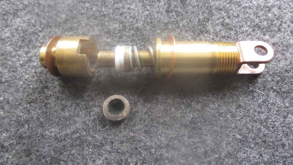
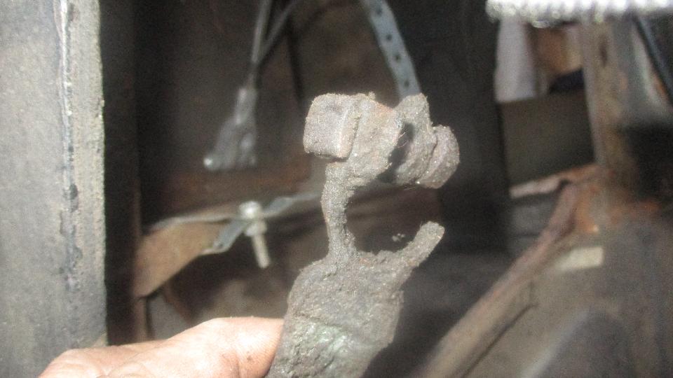
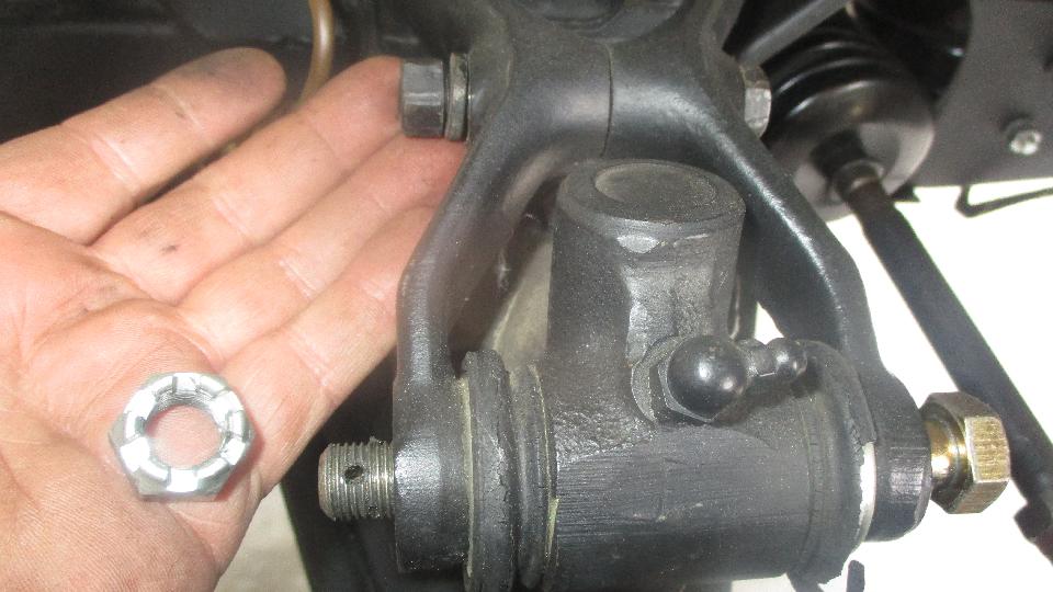
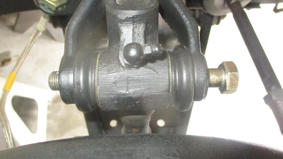
 The seals are applied to the ends of the trunnions with an orbital motion to get the seal lip to stretch into place. Then spread the shock arms a bit to get the trunnion assembly to slide in between. Shove a fat guide pin (big Phillips screwdriver) through the trunnion and wank it around to align all the holes (including the thrust washers inside), and then drive the big bolt through. Nut on, tighten the big bolt, install the nut locking split pin, and don't forget to tighten the smaller bolt in the middle of the shock arm. 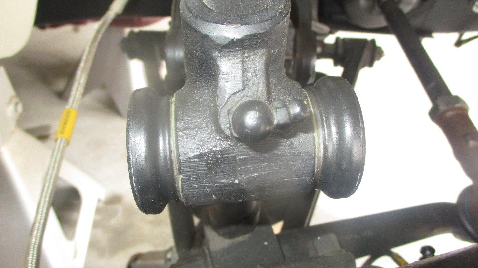
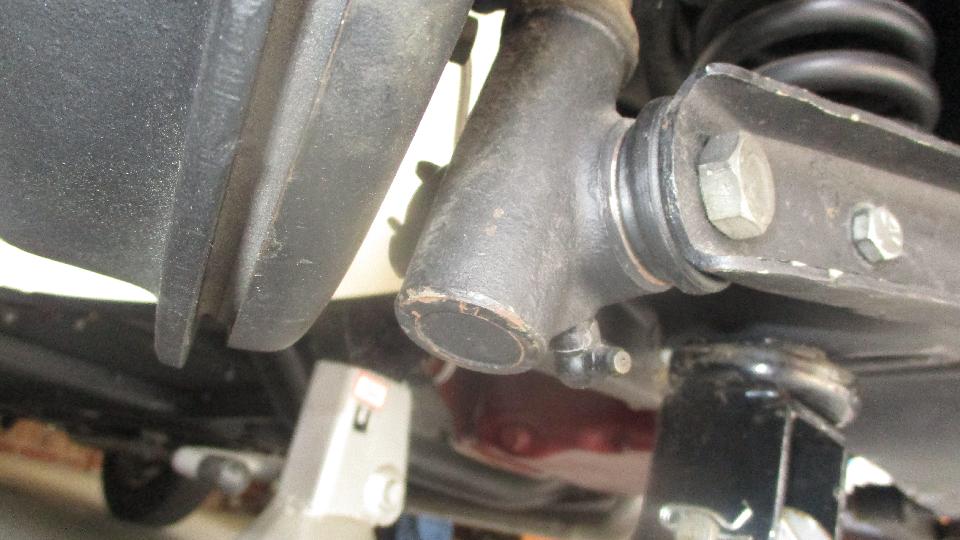
 Similar procedure for the lower A-arm, but loosen one of the small outboard bolts to free one side bracket from the the spring pan to be able to spread the arms. Remove the bid bolt, pull the lower trunnion free from the A-arm, and install the new seals on the trunnion. Spread the arm bracket a bit to slip the trunnion assembly back into the A-arm, align all the holes and drive the big bolt through. Nut on very tight, split pin installed to secure the big nut, tighten the smaller bolt(s) in the side brackets, and it's done. Gotta hate the rotten seals that had perished in storage, and hope the new ones are better now. Repeat all on the other side of the car. 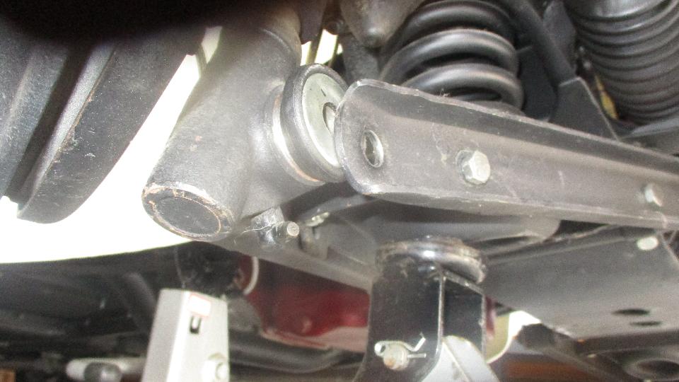
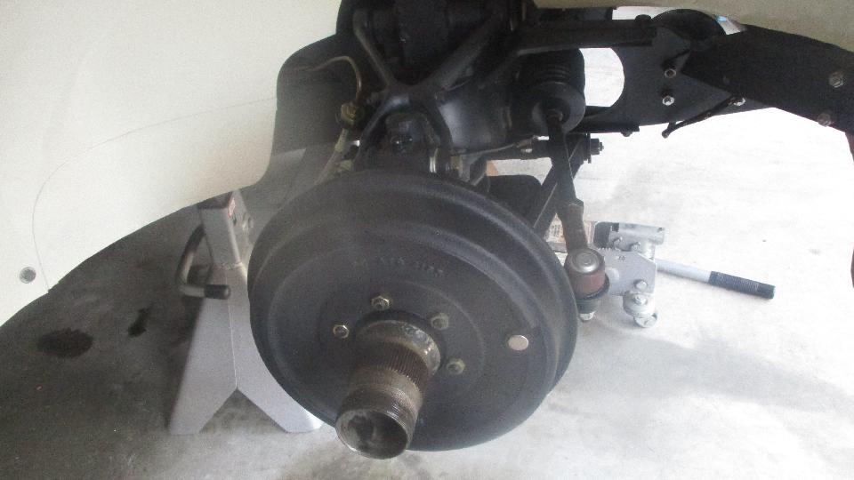
 During this process we were noticing a brake fluid drip from the LF brake drum, like one drip every 20 minutes (definitely not good). Pulling the brake drum off revealed a leaky wheel cylinder. Okay, bite the bullet and order up repacking kits for the front brake cylinders. Looks like another little chore for early next week. Reinstall the brake drum, put the wheels back on, and get it off the stands. 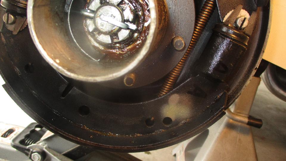
 We spent a little time realigning headlights and installing stubborn trim rings. I guess not much else, but it was enough for one afternoon. Back to WiFi with a huge backlog of clerical work pending.
 Thursday-Friday, March 29-30, 2018: Easy note. Two long days of catch-up work with four days worth of photo and notes, a couple days backlog of email and tech questions, new tech pages on the temperature gauge repairs, and I don't remember what else. Ansel's parts came in, so we will be back to the wrenches for the week end. Saturday, March 31, 2018: 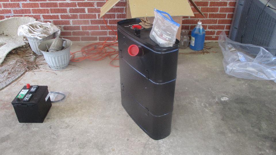
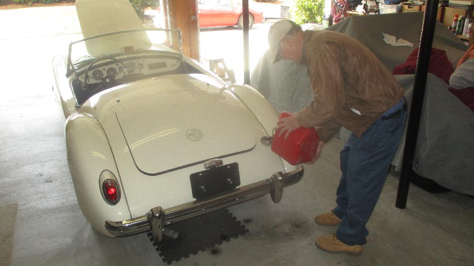
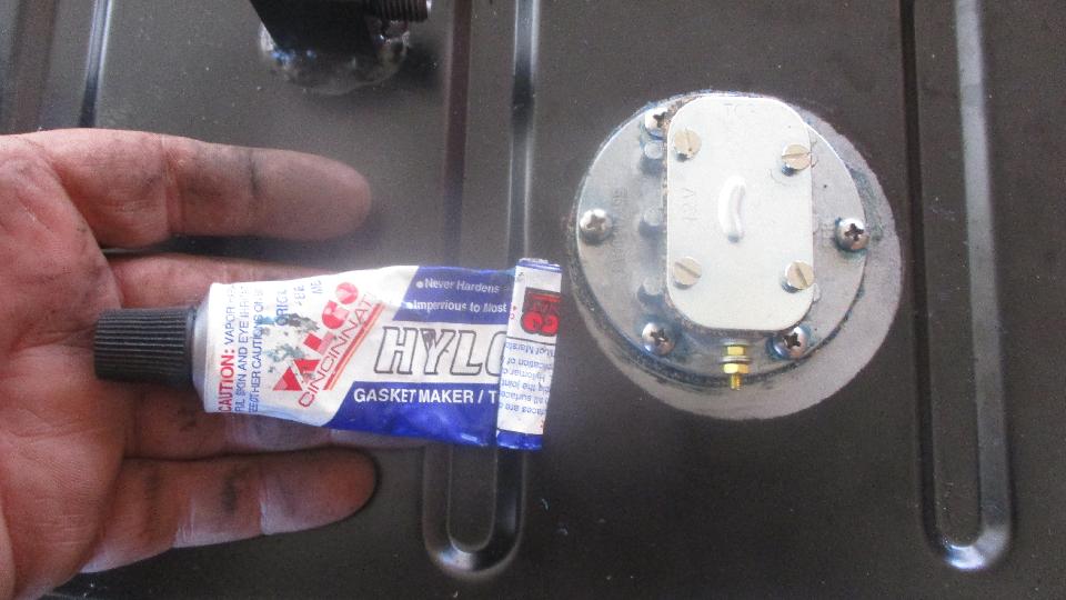
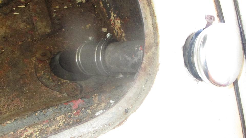
 Got a big box full of parts, in additional to a new fuel tank, so we are off to tinker on Ansel Gantt's MGA in Columbia, SC. Seems like I neglected to order the screw kit for the sender unit, but I did find six #8-32 screws in the magic trailer, various lengths but easy enough to cut down to suit. Instruction sheet for the sender unit was ballyhooing greatness of the Viton gasket, but a good old cork gasket was actually provided (which I think is better anyway). I stuck this all together with a thin smear of Hylomar gasket sealer. I think this was the first time I have actually used the stuff, but had it in hand, so good time for a trial. Cork gasket with tight fitting screw holes usually seals well without sealer. Good opportunity to R&R the seal retainer plate to install a new rubber seal on the boot floor around the tank filler neck. The impact driver got the somewhat rusty screws loose easy enough.
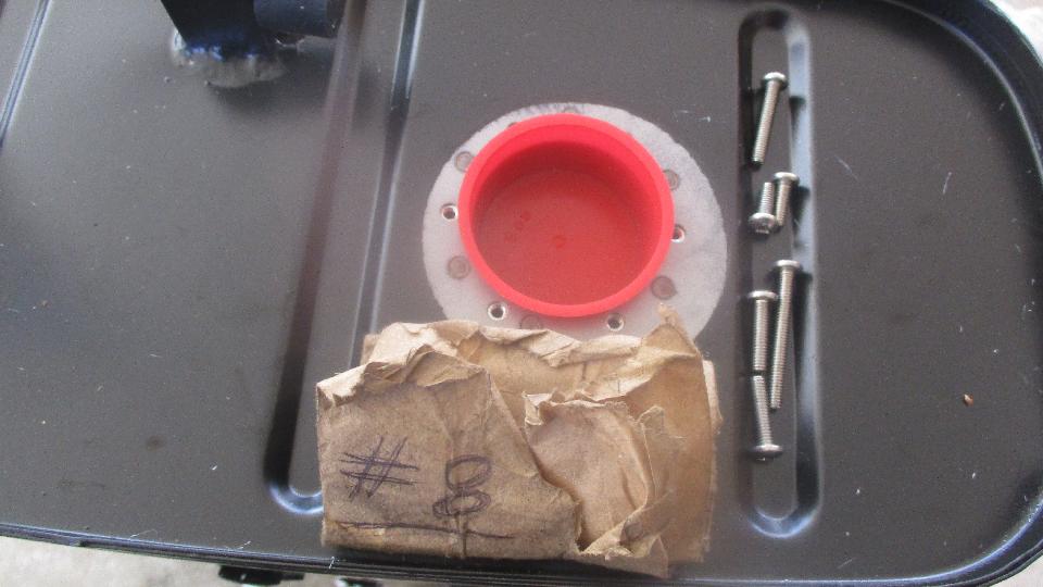
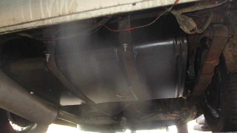
 I used a bit of blue stuff (RTV sealer) to glue the packing straps to the fuel tank prior to installation. Had new bolts in hand, so installation was easy enough (only a small fight). Seems like the filler pipe was located about 1/2-inch too far to the right. Strap guide clips on the tank seem to be symmetrical and in the correct locations, but when installed the filler pipe was smack up against the right side of the hole in the boot floor. That required a lot of trimming of the rubber gasket, and a little fight with the screws, but patience ultimately prevailed. 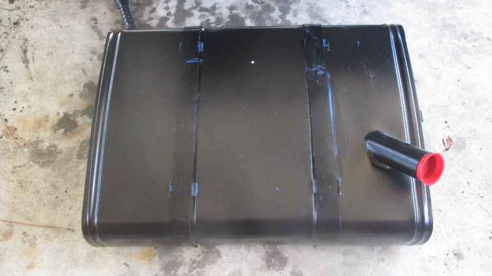
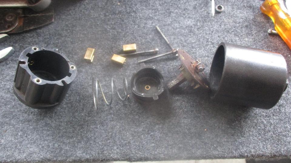
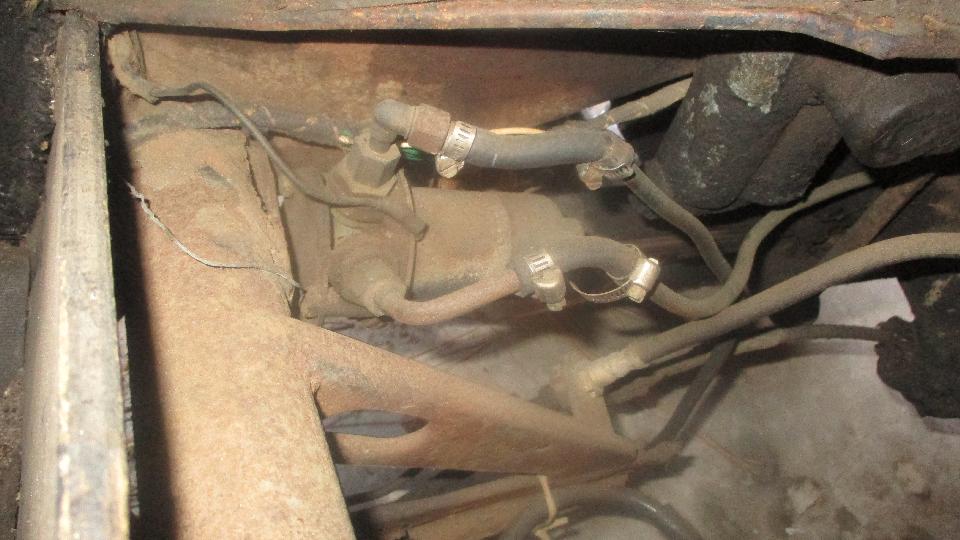
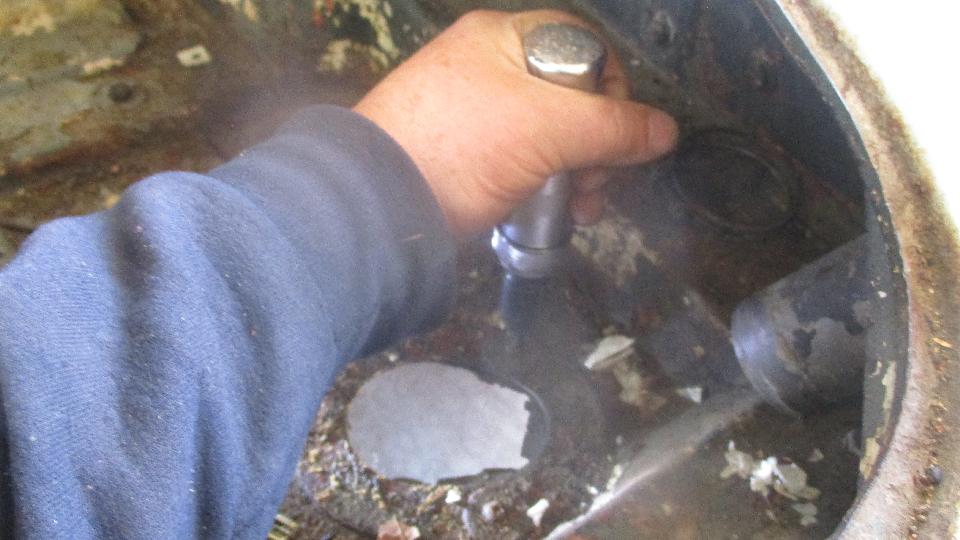
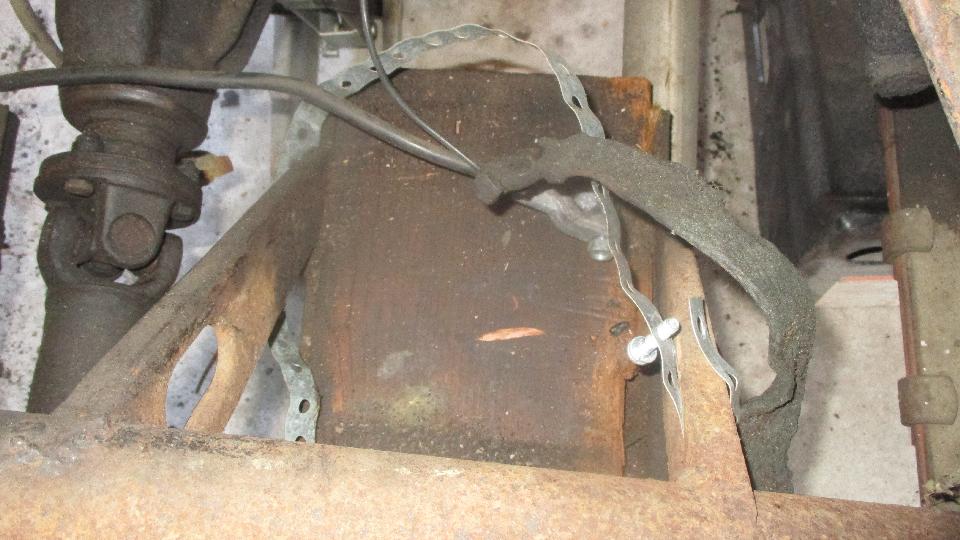
 Now there's an example why things sometimes take longer than expected. Sidewalk supervisors wanting to horn in on the tech session. Dave Daniel, Ansel Gantt, and Elliot Cox. Solution to that was to send a couple of them off hunting for a big P-clip for the new fuel pipe. The fuel pump lash-up was a bit of a mess. The curved pipe attached to the pump doesn't belong, and the hoses are at least a coon's age, and the pump was hanging on two loose bolts with no rubber isolators. And it was electrically dead, so pull it off for inspection. 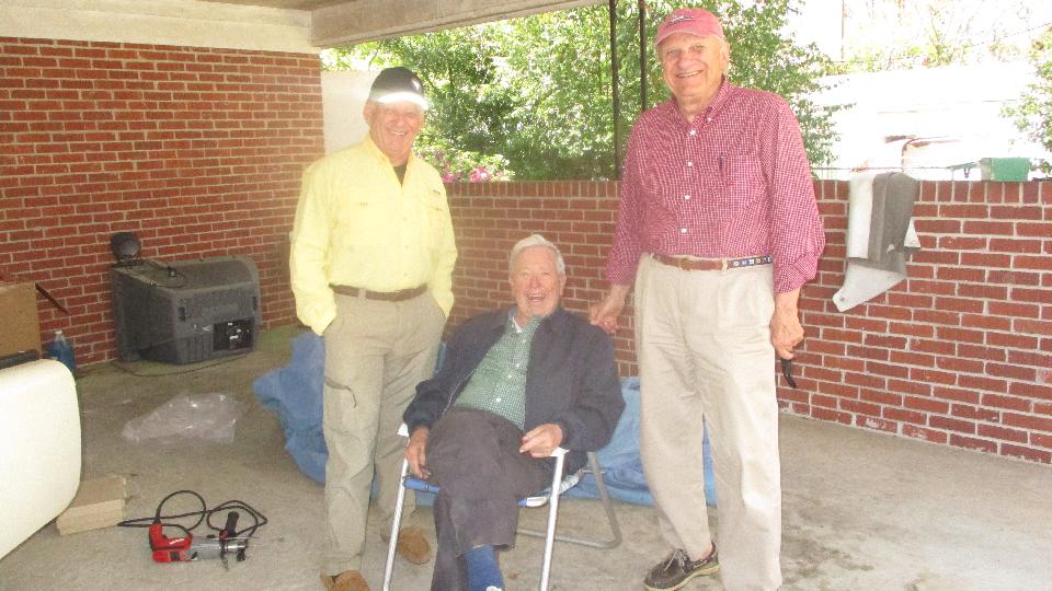
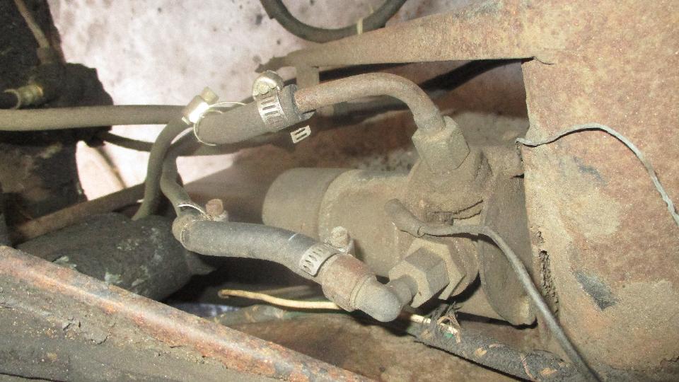
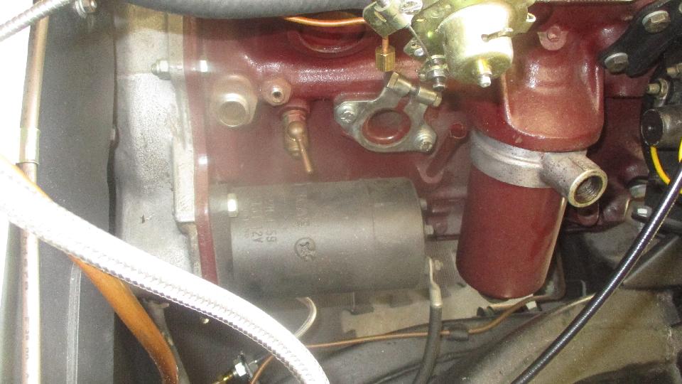
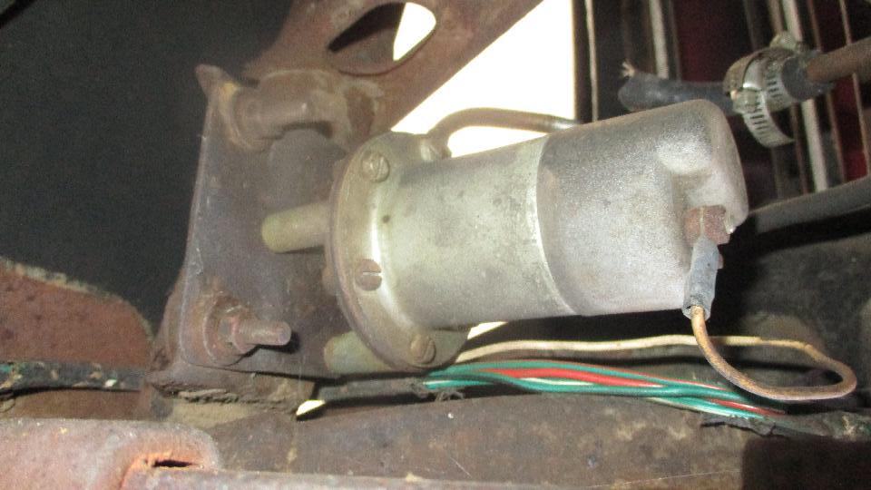 The fuel pump ground wire was attached to the tip end of the top floorboard screw with a hex nut. I know this is as original, but first time I have actually seen one there. It is a bear of a location for access with either wrench or fingers. Thinking maybe it was intended to be on the next bolt down, below the round frame tube. Once it was out, no problem to remove the end cover to clean the points with emery paper. Someone was here before, no tape on the cover joint. Capacitor across the points, so not polarity sensitive, golden opportunity to convert the car to negative earth. 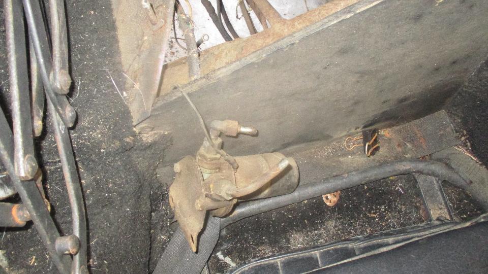
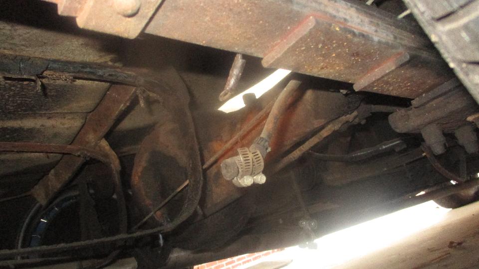
 New fuel pipe installed from tank to pump, all metal, no hoses. Cupro-nickel pipe, easy to bend by hand. 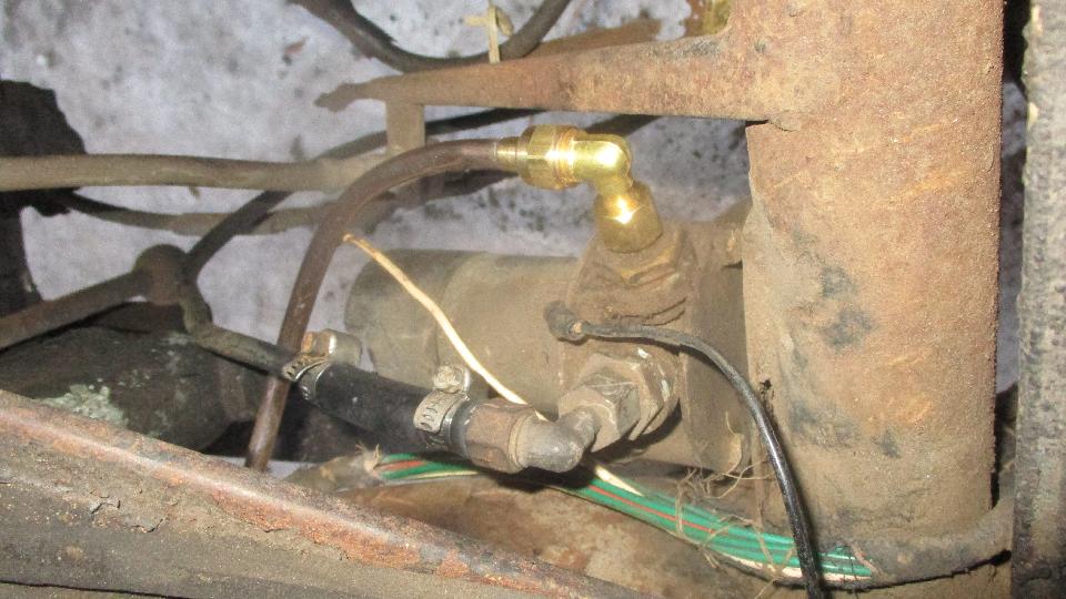
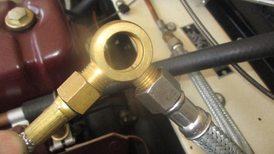
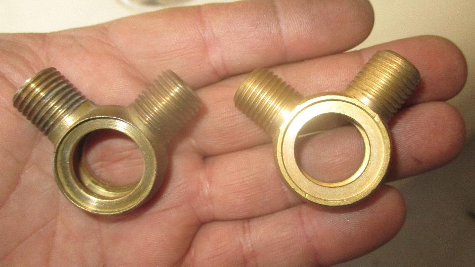
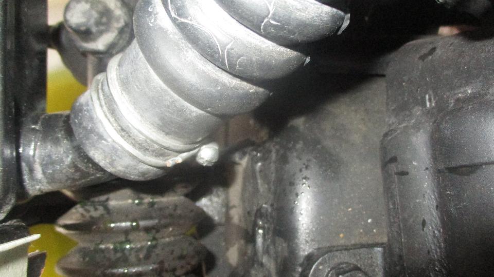
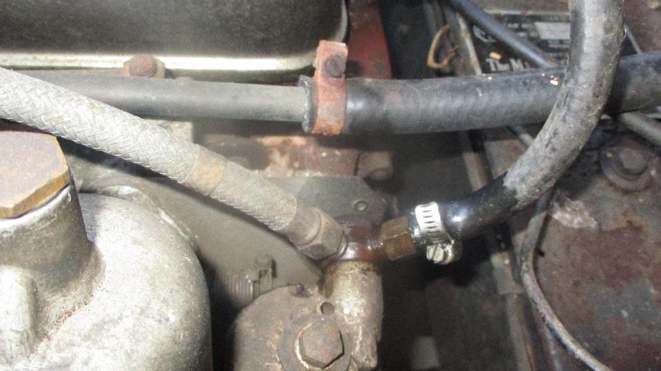
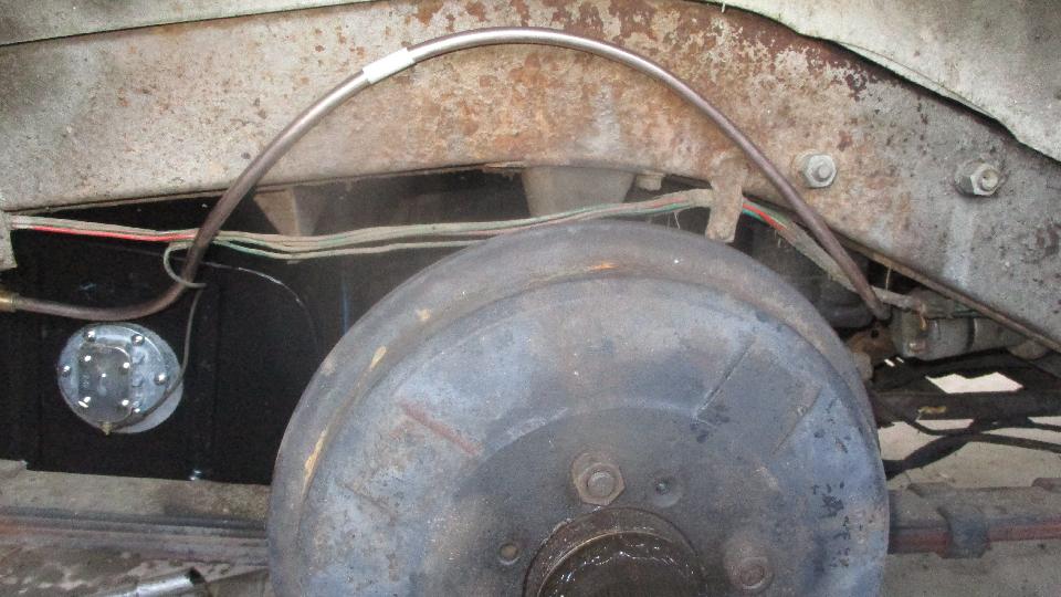 The large upward loop can change shape slightly to accommodate routing at end connections. Still needs a P-clip on the shock absorber rear bolt to prevent vibration of the pipe. Got rid of the rogue curved inlet pipe and hose connector in favor of original type right angle fittings with all metal connections. Came up one olive short of making the metal outlet pipe connection directly to the pump, so hooked it up with a new hose for now.
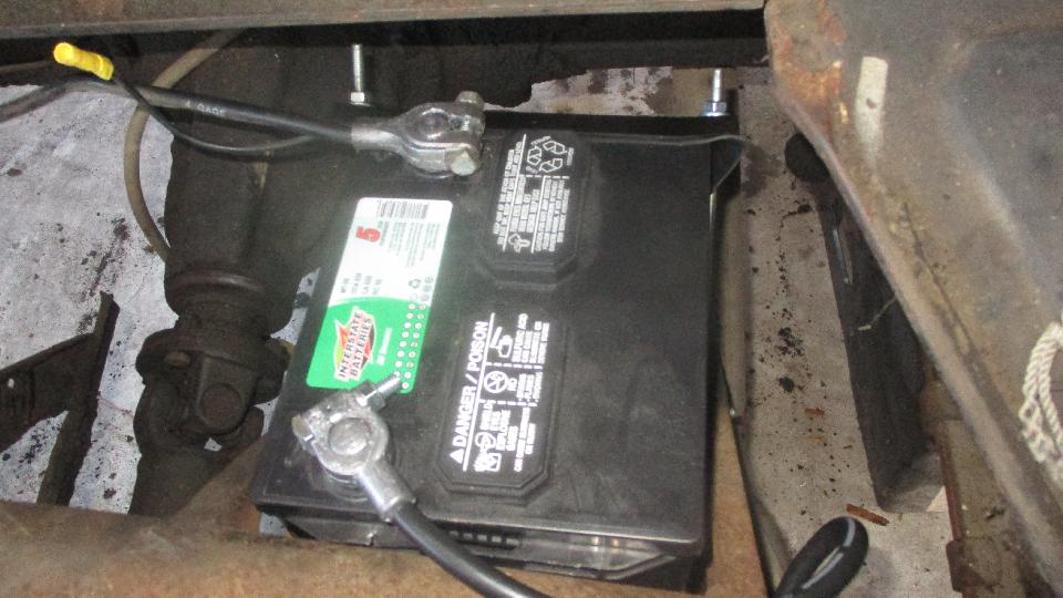
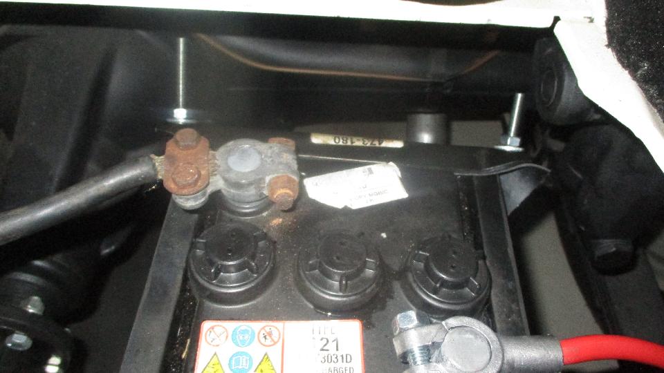
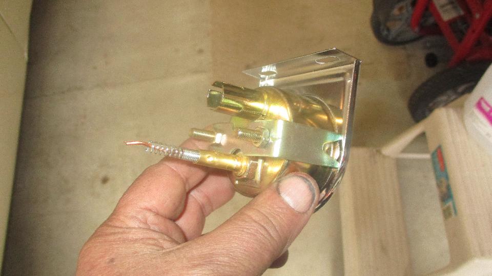
 J-bolts provided are all long (one should be shorter), and not enough threads, so run a threading die down the rods to extend the threads. Careful not to let the hold-down clamp touch the battery hot terminal. New grounding cable, and reform the cable terminals to fit large positive post and smaller negative post with connecting it for negative earth.
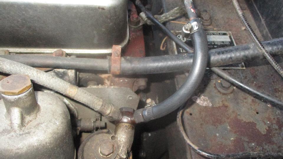
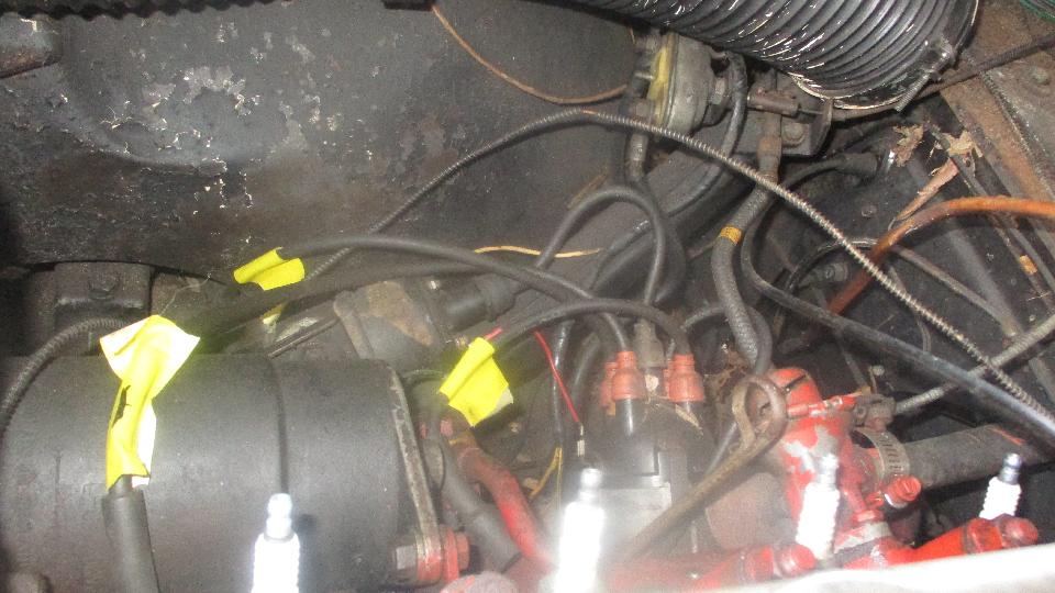
 switch off, replace a leaky connector hose at the rear carb banjo fitting. Switch on, ticky-ticky. Oops again, fuel dribbling from loose rubber grommets at bottom of float chambers. Switch off, leave the carburetor rebuild for tomorrow. But we did crank the engine over with plugs out, getting good oil pressure in short order. Thumb over the spark plug ports reveals very little compression on #3 cylinder, kind of expected when #3 plug had been oiled up in prior driving. The owner figures he may have been driving it on three cylinders for some time.
 |