The MGA With An Attitude
| MGAguru.com |
|
MGAguru.com |
MGA Guru Is GOING MOBILE - (November 16 - November 30, 2024)
Saturday - November 16, 2024:
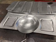
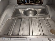
While waiting for paint to dry, I had time to update a Restoration tech page for Boot Floor Panels. You can now buy this one-piece restoration panel from Jon Thompson at Sports Car Specialties in Ada, Missouri.
Sunday - November 17, 2024:
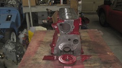
Strip off the masking tape and pull wadding out of ports and tapped holes. Looks ike an engine block with nice paint, so yes, begin assembly.
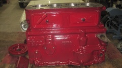
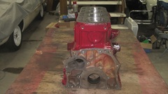
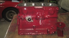 We oiled the inside of the block first, just in case it might be longer than anticipated before it might be running, and keep everything clean. Three main bearing half shells with oil,then the crankshaft nicely oiled all over. Three more half shells in the min bearing caps, center cap with thrust washers, give it a spin to assure it turns freely. Then the front and rear caps with more oil, and give it another spin with fingers. Notice this MGB 18G engine has locktabs for the main cap nuts,different than earlier engines that had lock washers here.
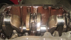
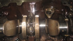
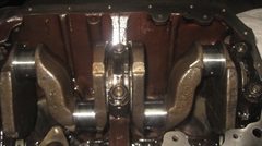
Oil the camshaft journals and heavily grease the cam lobes before sliding the cam into the block, then test spin with fingers. Temporary fit the front plate, and scribe the rear surface at sides of the block.

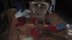
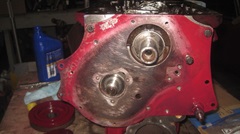
Remove the front plate to remove paint from the rear side where it will mate with the paper gasket, just to assure it will have flat surfaces for a good seal (not gasket over paint). Install the front plate with paper gasket and the cork strip at bottom corner of the front main bearing cap. RTV sealant was applied, because this cork seal had small end gaps. Once it was bolted firmly in place, we trimmed the cork seal flush with a razor knife.
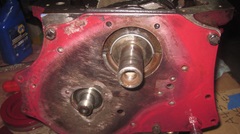
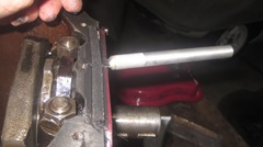
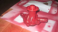
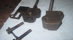
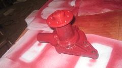 Take a short break to paint a new MGA water pump, as it was the net thing out of the box. Then we encountered an odd problem with a new timing chain tensioner, something I had never seen before. The traditional tensioner shown at top of next picture, with the new tensioner immediately below. The new one is three pieces only, no backing plate, no gasket, no bolts or locktab, no internal anti-back out step cam, no rear plug or locktab. Also no alignment spigot at the oil inlet port, and no drill hole to allow oil through the rubbing foot to lube the foot and chain. Additionally, the rubbing foot is made of soft plastic you can impress with a finger nail, or poke a hole in it with a screw driver. I am skeptical if this new tensioner can be functional or if it might last more than a few thousand miles before self destruct. And "Made In Taiwan" is not reassuring.
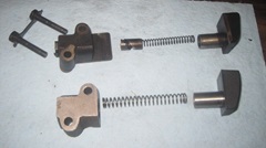
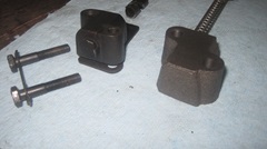
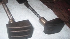
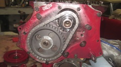
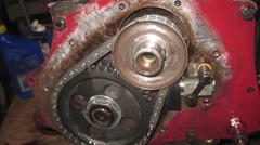
I will set this issue aside for more consideration over night. Meanwhile we did install the camshaft retaining plate and timing chain and sprockets (sans tensioner).
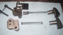
Monday - November 18, 2024:
I placed an order with Moss Motors this morning for a new Rulon timing chain tensioner (along with a few more parts). I have so far never been bitten by failure of this part, and I don't like the idea of installing another skeptical looking cheap replacement part with unknown service record. I also called the vendor to offer my comments on the odd new tensioner. Of course the response was that we have never heard of any problem with this part, and I'm the only person to ever report any concern with it. The rest of the conversation was not encouraging (or convincing). The new style part is supposed to be from a Datsun 1500 Roadster engine. I just don't feel like serving as Guinea Pig on this one. Been having too many other poor quality parts problems recently. -- Much of the day spent posting the photos and notes above, and there was a John Twist Zoom tech session this evening on "Setting up MGB Front Wheel Bearings".
Tuesday - November 19, 2024:
Big surprise. The Moss order placed and shipped on Monday arrived Tuesday afternoon, one day delivery from UPS. As it was projected to be 2 to 3 days, I wasn't looking at tracking information, so didn't know it was here until Wednesday morning.
Wednesday - November 20, 2024:
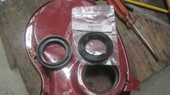
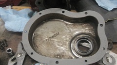
Back to work. Punch the old oil seal out of the timing cover to install a new seal. Notice this early MGB timing cover is same as late MGA 1600-MK-II style, with the seal inserted from outside. As such, it uses the same cup shape oil thrower ring as all MGA. We cleaned some paint off of the engine front plate to assure that the paint wouldn't interfere with the cover gasket.
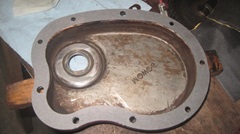
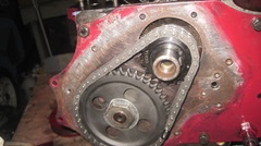
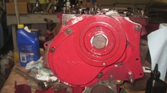
We installed a new timing chain tensioner, Rolon brand, similar to the OEM part, and put the oil thrower in place before closing the cover. install a new gasket with a little sticky stuff, and install the cover with loose screws. Install the crankshaft cover temporarily to centralize the cover seal on the pulley hub. Tighten a few screws to hold the cover in place, then remove the pulley before tightening =all of the cover screws, and reinstall he pulley. In this case we installed the harmonic balancer that was original for this engine (beginning mid production of the 18GA engine), with a new locktab and original hex head bolt (for now). Left the bolt loose and locktab not set, anticipating installing the MGA dog nut here (once it comes out of the car) so we can continue to use the MGA starting handle.
Roll the engine on its side and get on with installing pistons. While removing the old pistons from the conrods, #2 gave us some problems. The wrist pin was seized so tight in the piston that it wouldn't move tall. We ended up clamping the piston in a vice and hammering the conrod to move it to one side for access to the pinch bolt. Then lay the piston on its side and use thick punch and heavy hammer to drive out the wrist pin. After that ordeal, the old piston was dropped into the nearest dust bin, along with the rest of the old pistons. Installing new pistons on the rods, installing rings on the pistons, pushing pistons into cylinders and connecting big ends with oil in the bearings was more standard fare. We soon had a new oil pump and pick-up screen installed, as well as the pressure relief valve and side plug. The crankshaft still turns easily with a short lever and one hand, with only nominal resistance from new springy piston rings dragging on freshly honed cylinder walls.
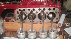
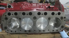
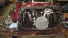
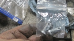
I was going to install the new water pump when we discovered the new bolts procured with a recent parts order were all too short. The two longer bolts were close enough to use in place of the two short bolts. Hunting for longer "long' bolts when we decided to call it a night and come back tomorrow.
Thursday - November 21, 2024:
Back to work on engine assembly, we're getting there. Finally found some 1-3/4" long bolts for the water pump, ran out of threads in the blind tapped holes in the block. Ground 1/8" off the tips to make 1-5/8" long. These bolts could be a smidge shorter, maybe
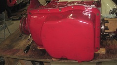
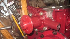 1-1/2" would be good. -- Installed the sump temporarily with six screws, no gasket. Thinking we may need to install the cork seal strip at back and bolt on the engine rear plate before final installation of the sump, but the rear plate we need is still in the car until we will pull the old engine out. And we ultimately want to set the engine upright before installing the right side engine mount parts. Still thinking about how to install the sump with rear cork strip before the rear plate.
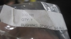
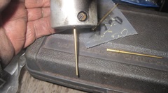
 Time to replace the spigot bushing in rear end of crankshaft, as the clutch alignment tool would wobble some in the old bushing. I pulled out a new busing just received from Scarborough Faire, slipped that onto the alignment tool, and the new bushing wobbled some on the tool. Say what? The new bushing also looked a bit rough,not as smooth as I am used to seeing for a good Oilite bearing. Measuring the bushing ID with a dial caliper shows the bore to be 0 .629" where it should be 0.625 to fit with the 0.623" spigot on the gearbox input shaft. Curses, out of spec bushing. We then pulled a spare bushing out of the Magic Trailer. That one had a Moss Motors part number, looked smooth, measured 0.625" ID exactly to spec, and fits well on the alignment tool. We will install this one, and see how far I can throw the out of spec S/F bushing. Time to replace the spigot bushing in rear end of crankshaft, as the clutch alignment tool would wobble some in the old bushing. I pulled out a new busing just received from Scarborough Faire, slipped that onto the alignment tool, and the new bushing wobbled some on the tool. Say what? The new bushing also looked a bit rough,not as smooth as I am used to seeing for a good Oilite bearing. Measuring the bushing ID with a dial caliper shows the bore to be 0 .629" where it should be 0.625 to fit with the 0.623" spigot on the gearbox input shaft. Curses, out of spec bushing. We then pulled a spare bushing out of the Magic Trailer. That one had a Moss Motors part number, looked smooth, measured 0.625" ID exactly to spec, and fits well on the alignment tool. We will install this one, and see how far I can throw the out of spec S/F bushing.
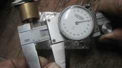
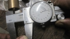
I have this neat tool for pulling the spigot bushing with a slide hammer. I think it was originally a fender pulling hook. Many years ago I ground it down for this special application. First used to pull a 15-mm needle spigot bearing from a Mazda RX7, it is a tad small for the 5/8" bushing, but still works a treat.
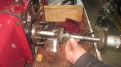
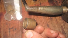
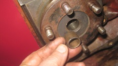
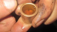
There is a neat trick for installing an Oilite bearing, so you don't need to soak it in oil for 24-hours. Set the bearing on end on your finger tip (or thumb), and fill it to he top with oil. Place thumb on top to seal it, and squeeze until you see the bearing "sweat" through the porous sides. Instant lube for the Oilite bearing ready to install immediately. Push or tap the bushing gently into place. Start with a flat face tool to drift the bushing in until flush, then you can use a wrench socket to drift it home to the shoulder in the crankshaft. With oil on the clutch alignment tool it should be a perfect fit, no wobble, and a nice vacuum tight "pop" when you pull the tool out. If you accidentally put a small burr on the edge of the bushing bore, it can be easily cleaned out with a rat tail file, no need to use a 5/8" reamer.
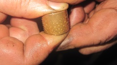
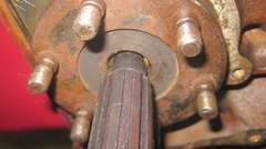
Time to install the tappets. We have kept them in order with numbered tape on each one, although it likely wasn't necessary here. Pretty sure this reground cam and new tappets have zero running time, all new stuff. Notice the tappets are ground with a slight crown on the "flat" end. With a thin film of oil it gives a nice mirror reflection of my fingertip. Oil the bores and the tappets, and drop them right into place.
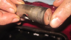
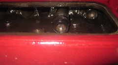
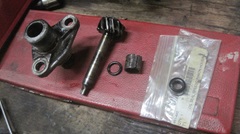
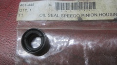
I was going to install a new shaft seal in the tachometer drive housing when I began running into some dead ends and confusing blind corners. the tachometer drive housing on the engine can,in theory and in common practice, use the same seal as he speedometer drive housing in the gearbox. It should be 5/6" shaft, 9/16" housing bore, 1/4" wide seal. BTDT multiple times with my MGA, both speedo drive and tach drive. I have (had) a spare seal in the Magic Trailer since five years ago (procured from Moss Motors), and I recently ordered another one from Scarborough Faire (which was maybe missing from the package on delivery). While navigator was pulling the spare seal out of the trailer, I was disassembling the tach drive from the MGB 18G engine, removing the shaft, seal retainer and seal. The seal removed looks like a standard O-ring (hard as a rock), tight on the shaft but loose in the housing. Guessing this is not factory issue. -- The new seal was correct size to fit in the housing, and he pinion gear shaft of course fit in the housing (because I had just pulled it out). But the shaft did not fit through the new seal. Huh? Measurement shows the MGB tach drive shaft to be 3/8" diameter, and the housing bore as well.This means the tach drive shaft and housing and seal have to be different part numbers for the early MGB 3-main bearing engines. Go figure, new to me, and I don't have a seal for it. -- Seems like the expedient fix will be to transfer the tach drive assembly from MGA 1600 engine to MGB 18G engine. If I do that, there will be forever the issue of keeping track of which parts were used to build the Frankenstein engine. And this will suck up more time for documenting the dimensions and part numbers for the MGB tach drive parts. Such is life.
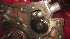
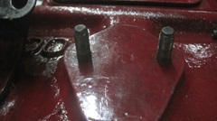
Still going, we installed the head studs in the bock, and the left side engine mount bracket and rubber mount. Installed threaded studs for the tach drive, and on left side of engine in the dummy (blank not machined) space for a mechanical fuel pump (not used for MGA or MGB). These studs are used to attach the draft pipe and fuel vent/overflow pipes from the carburetors.
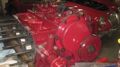
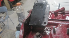
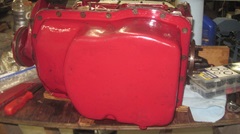
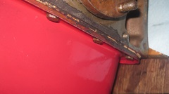
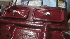
I finally figured out how to handle the cork strip seal at he rear main bearing cap to sump gasket joint prior to installing the engine rear plate. Bit of finesse to insert the strip seal on edge, slobber sealant on it and hold it in place (push, push, push) while tightening the sump bolts. I used a thick cork gasket for the sump, gluing the gasket to the sump flange with sticky stuff, and greasing the top side of the gasket for easy release next time it might be removed. -- The tappet covers got new bolts with rubber covered flat washers and silicone rubber gaskets (Michael had them handy). I'm usually happy with cork gaskets here, but the cork parts seem to shrink a lot in storage making them sometimes difficult to install if they are not fresh issue. A few years go I had to make my own cork gaskets from two layers of 1/8" cork hand cut and glued together, kind of a pain. So in the future I may carry silicone tappet cover gaskets for spares.
Friday - November 22, 2024:
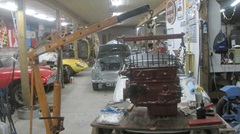
Day to assemble the engine hoist, get the tackle hitched up and lift the engine upright. After a couple different configurations, we settled on the tilt-leveler connected to front and rear head bolts (still with no head).
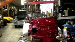
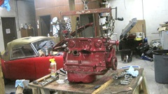
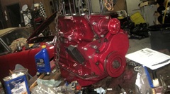
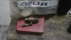
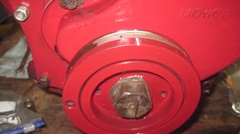
The important bit was to install the right side engine mount. We decided to ditch the water drain cock from the engine block and install a brass hex plug there, since we could never get the drain port clear, and I haven't ever used it anyway. The OEM drain cock works,so I guess we will hang onto it while it is looking or a new home. There were a few more minor details, like painting the timing marks on the crank pulley. I was installing the distributor drive gear when I thought it might not be properly oriented. Then I was trying to check/verify cam timing with two screwdrivers on top of tappets while turning the crankshaft. It still looked confusing, like cam timing might be one tooth late on the timing chain. even though I'm sure we had the sprocket dots lined up right. I have seen improperly marked sprockets before. So now we intend to install the head and rocker assembly before passing the cam timing inspection. That will be a job for tomorrow, to pull the head off the engine in the car and swap it over here.
Saturday - November 23, 2024:
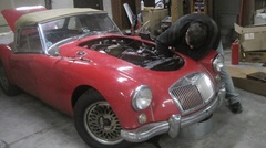
Early morning finish posting photos and notes from yesterday. Late morning start, we need the cylinder head next. Just a few minutes to remove thumb screws to extract the bonnet and set it aside for good access to the engine bay, and get busy draining engine oil and coolant, remove hoses,and pull the radiator out. Since we commonly change a head gasket in two hours, it only took an hour to remove carbs and manifolds, lift off the head and set it on the bench next to the new engine,
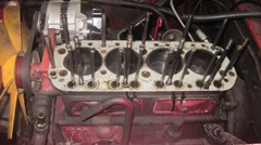
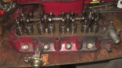
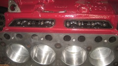
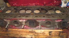
At every opportunity, flip the head over for inspection in the combustion chambers. the exhaust valves are nice tan color, same as the spark plugs. Intake valves a little darker, but no accumulation of carbon, so it appears the engine has been running with correct fuel mixture, all is well here. We know there was low compression on #3 cylinder, we think most likely a bad piston ring (check that later). Now be sure the head is sitting level, and fill the combustion chambers with water, to the brim please, and wait a few minutes. Then grab a spot light and check the side ports so see if any of the valves might be leaky. Hard to get a good picture in a slightly sooty exhaust port.
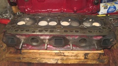
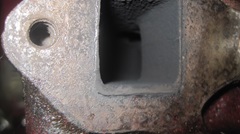
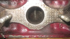
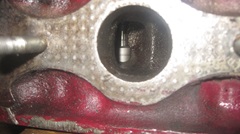
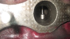
Better view into one of the siamesed intake ports. Good news all around, not a drop of water in any of the ports, so this head is good to go, ready to get back to service. Mop the water out of the chambers and get it off the blocks.
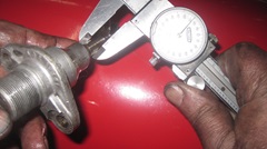
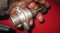
then we retrieved the tachometer drive assembly from the engine in the car specifically to measure the spindle. Result is 0.374", same as the one that came with the 18G engine. The one from the old engine has a good seal that has not leaked since it was installed three years ago, and we generally have never had leaks from the tach drive, so this one will be installed on the new 18G engine. With this issue resolved, I will have to revise a couple of tech pages to show the seal as having 3/8" ID (not 5/16" previously noted).
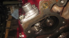
Time to install the head. Clean top of block, slap on a new head gasket, and install the first and last pushrods. When we set the head on we immediately discovered a problem, the pushrods were too long. OOPS! ... Dang. Seems like every time we install a new cam and tappets, the new tappets are different length and require changing the pushrods. It's a long story, but the engine in the car has short bucket tappets from a later MGB 18V style engine, and the longer pushrods to match. The new 18G engine came with new (reground) cam and new original style long tappets but no pushrods. We could take the 2-year-old cam and short tappets and long pushrods out of the old engine to install in the new engine, and save the reground cam and long tappets for later use, but we don't want to take the new engine apart again to swap cams when all we need is set of short pushrods.
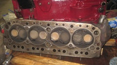
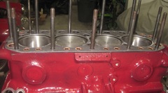
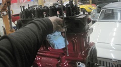
Well low and behold, not ten steps down the hall lies a Datsun Sports Roadster in mid restoration with engine disassembled in process. From 1959 to 1970 these could be 1500, 1600 or 2000 cc engines (production licensed from BMC). Sitting on the bonnet was a set of short pushrods, really. After short consideration, and one phone call for approval, we will snatch those slightly crusty short pushrods for now and buy him a new set later.

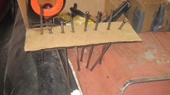
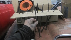
It didn't take long to run a wire wheel over the pushrods to buff off some crusty dried oil and polish them up for good service. The short pushrods were installed and the head set in place with three head nuts to secure it temporarily while adjusting the valves and checking valve timing. Timing chain is installed properly, and cam timing is correct, so all is well with the world.
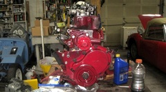
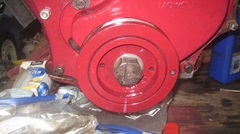
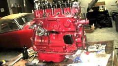
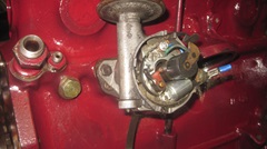
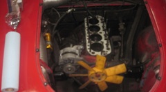
Not too long then to install the distributor drive gear, base casting, clamp and distributor, adjust points and preliminary static timing. Dipstick tube installed, and two fittings for the oil pressure signal hose connection and main oil outlet fitting at RR corner of the block. A quick check on the distributor drive, we will install the rest of the bead bolt nuts and torque down the head tomorrow. Chilly in the shop, so good time to knock off for the day. Tee old engine in the car looking a bit forlorn.

Sunday - November 24, 2024:
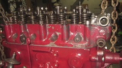
Time to finish dressing the new engine. install all of the head stud washers and nuts, and torque them down gently for now. Clean out out threads for alternator rear bracket bolts. Install a new heater valve, sine the last one n was well beyond its projected 2-year max life expectancy.
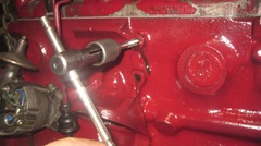
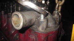
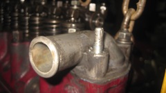
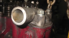
Fix another significant issue which we could have left untouched, but better fixed in comfort not to be stuck somewhere else later, Having replaced special threaded thermostat cover studs two years ago, the new ones were faulty soft steel, and one of them had stripped the threads. The expedient solution at the time was to double nut the stud so the top nut was holding the load. The double nuts could not be jammed together to extract the stud, so remove the nuts and have at it with a Vice-Grip. Fortunately we had ordered better quality studs from a different source, just took a while to find them, and that was soon back in order.
Install the alternator rear bracket and the engine number tag tat was original to this 18G engine. Snatch the spin-on oil filter adapter from the car engine and install it here. What it still needs is a low starter engine rear plate and flywheel and clutch, but those parts are still in the car. So hoist then new engine off the table and set it aside for a while.

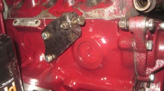
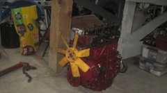 C
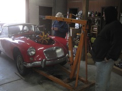
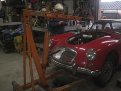
Bolt the tilt-leveler to the engine in the car, remove bolts from engine mounts and bellhousing, lift and pull, and the old engine was soon out of the car. C
Bolt the tilt-leveler to the engine in the car, remove bolts from engine mounts and bellhousing, lift and pull, and the old engine was soon out of the car.
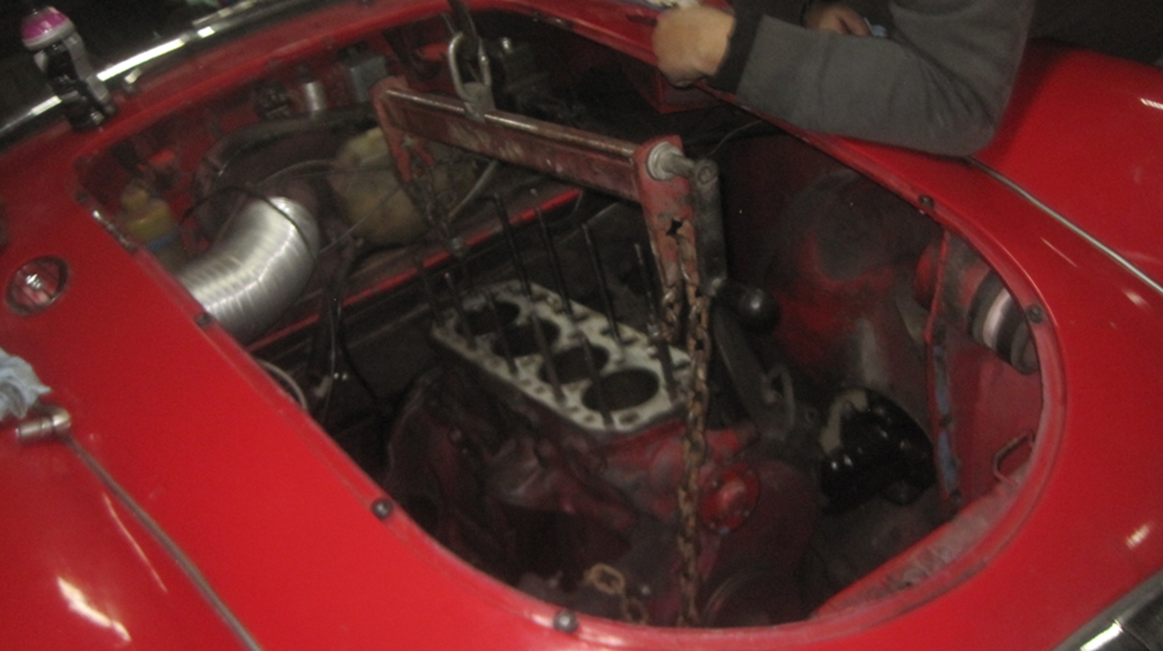
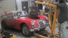
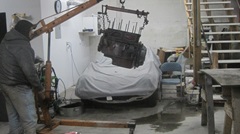
Set the old engine on the table and remove some parts that are to be transferred to the new engine. We snatched the crank dog nut, and took the relatively new MGA crank pulley as well.Getting close to decision time if we will use the thinner riveted pulley or the newer issue thicker harmonic balancer. Clutch, flywheel and rear plate are next off.
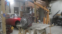
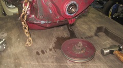
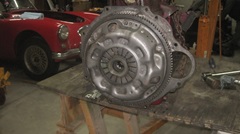
Just six bolts to extract the pressure plate and friction disc. They may be a little oily, but should clean up nicely, and look well otherwise.
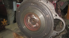
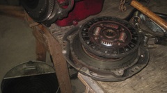
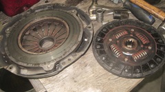
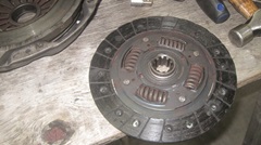
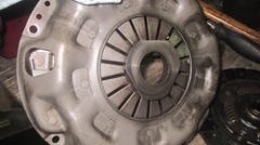
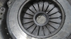
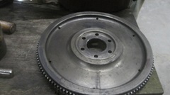
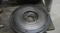
Locktabs and six more bolts get the flywheel off, also looking good to continue use after cleaning. Another 13 bolts to remove the rear plate, and some scraping to remove the gasket. This was followed by nearly an hour of scrubbing with stiff brushes and lacquer thinner. All the rear parts are fine, just not sure the block will ever be clean again. We have what we need now, so set the remaining 1600 short block assembly aside to decide later if we might disassemble it more to save some good internal parts.
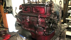
Time to knock off for the night, as we need a quick shopping trip.
Monday - November 25, 2024:
The minimal goal today is to finish dressing the new engine and get it into the car and bolted down. Probably not going to get it running yet. So lift the old engine off the table, set it on a rolelr dolly, and get the new engine back on the table.
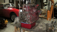
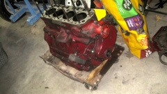

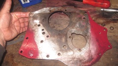
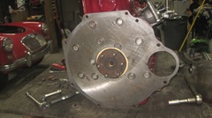
Get the grounding cable attached before we forget it, then the rear plate with gasket,and the flywheel. Interesting feature on the rear plate. Look closely on the rear plate around the crankshaft rear flange to see four small drilled and tapped holes with #8-32-UNF screw threads. Also the center bore has been enlarged slightly (see part of the gasket exposed). This was done in the mid 90's when I first designed and installed a rubber rear seal for the 3-main bearing engine (because it was dearly needed at the time). That engine was retired in 1997, and successive engines have not needed the rubber seal, but the same rear plate is still in use 30 years later. In fact this is still the factory issue original part from 1957, as this car has always had a low starter gearbox.
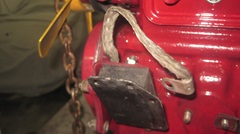
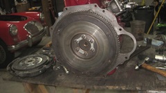
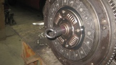
Set up the clutch friction disc with a (cheap) clutch alignment tool. Do get it the right way around, with the extended hub toward the pressure plate. Then install the clutch cover (pressure plate assembly) while carefully centering the disc. When done properly the alignment tool will slide in/out with one finger light force.
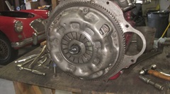
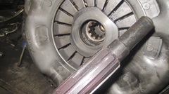
We removed the MGB harmonic balancer to install the MGA crank pulley. While the balancer pulley is a good idea, I prefer the thinner sheet metal pulley, primarily because it clears the steering rack easier when getting the engine in or out of the car (a very close pass at that point). And we install the MGA crank dog nut as well, to continue to enable use of the MGA starting handle.
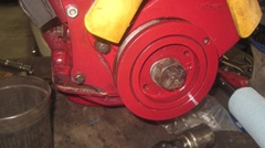
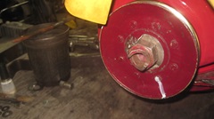
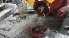
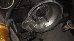
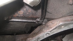
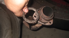
Verify that the MGB clutch release arm and release bearing are still in good condition, and clean the bellhousing ready to accept the engine with MGB flywheel and clutch parts. A close look at the P-clip with rubber liner securing the speedometer cable to upper corner of the tunnel. This is very important to prevent trapping the cable between the tunnel and bellhousing when the gearbox is lifted to max height to align with engine during installation. Believe me, everything is squeaky close passage (remember the preference of crank pulley). There is a trolley jack under the gearbox keeping it raised to intimate contact at top of tunnel. This will stay in place until the engine is mated to the gearbox with the first two bellhousing bolts in place and tightened. -- Dig out the exhaust pipe to manifold donut seal to install a new one while this is easy access.
3:10-pm 11/25/24 - Change of aspect ratio for the pictures for the rest of the day. Sorry, the camera mysteriously rest itself.
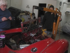
It helps to have extra hands for lowering thee engine to mate it with the gearbox. That's Michael Crews taking pictures with short pauses in the action. The engine needs sufficient tilt to lower the rear to slip the clutch cover over the gearbox input shaft while the oil pan is touching the suspension cross member and the crank pulley is squeaking past the body air pan and the steering rack. Moving farther back,the tilt angle is leveling out as the nose goes down. when the gearbox input shaft spline touches the spline in the friction disc, the engine must be strictly in axial alignment with the gearbox. To get the splines to engage, select 3rd or 4th gear so the input shaft cannot rotate, then turn the crankshaft with a big wrench in front while gently rocking and pushing engine to rear. do not rush or force it, just a matter of patience and finesse while the splines will ultimately slip together, and the back plate moves closer to the bellhousing (about an inch to go).
Finally the gearbox input shaft spigot end must enter into the spigot bushing in the tail of the crankshaft. This is a very close fit with just a few thousandths of an inch running clearance (with a new bushing). I put a 2-inch long bolt in one of the holes from rear plate to bellhousing with finger tight nut, to keep things from backing out while we gently jiggle the engine a bit. Then it magically slides together and goes "plunk" with the rear plate against the bellhousing. -- Then install two key alignment bolts. The first one will be top right near the oil outlet fitting on the engine. The second bolt will be diagonally opposite, bottom left. Those two locations have smaller diameter pilot holes for best alignment of engine to gearbox. Once those two bolts are installed you can tighten them up. The rest of the holes have more clearance, so the other bolts will then slip in easily to finish securing the engine to gearbox.
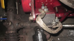
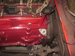
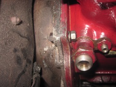
With engine bolted securely to gearbox, we can remove the trolley jack under gearbox and lower the engine to install eight small bolts in the engine mounts. Sounds easy, but maybe not. New rubber engine mounts have a mind of their own, and may require a fair amount of finesse and encouragement to get the mounting holes to line up, but just a matter of grunt work. Get the ground strap connected across the left side engine mount.
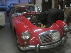

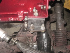
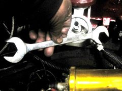
Getting hyped now, anxious to see if this thing can make oil pressure. Connect the oil cooler hoses and the signal hose for the pressure gauge, and install an oil filter. Michael used to be a Formula Ford mechanic at the race track, so he has this beautiful special 15/16" double end wrench for working the oil cooler connection fittings. Torque down the cylinder head , adjust the valves, install the valve cover, and fill it with oil.
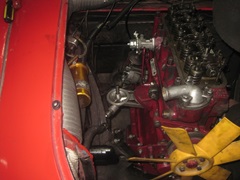
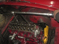
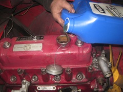

This was the moment that it dawned on us that we had not installed the starter motor, which should have been done as soon as the engine was bolted to the gearbox, or after the engine mounts were secured. Now the oil hoses are in the way making access more difficult, but again just grunt work to install the small gear reduction starter and connect battery cables and the trigger wire connector. A final check around, and switch on the battery disconnect switch.Get the stop watch, you keep an eye on the engine bay while I crank it and watch the pressure gauge. From prior experience, expecting 45 seconds to see pressure, maybe a bit more this time as we had blown oil out of the oil cooler early on, now now being full of air. We cranked for one minute, no pressure. Cranked it for another 30 seconds, still no pressure? Being a bit concerned, I disconnected the oil cooler hose at the engine oil output port,and there was oil there. Put it back and disconnect the cooler return hose at the oil filter, and there was oil there too. Put it back and disconnect the oil pressure signal hose at output end. No oil there? Put the signal hose in a catch vessle and crank the engine some more. Ten seconds more cranking, and we had oil flow at the signal hose. Yahoo! Reconnect it and get back to watching the pressure gauge while cranking. And we have oil pressure. Peachy. All together I recon two minutes of cranking this time, just took me by surprise, but all is well with the world. Enough for one day,take a break. We should get it running tomorrow.
Tuesday - November 26, 2024:
We have a sealed engine and good oil pressure. Time to mount the intake and exhaust manifolds and connect the exhaust pipe.
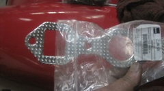
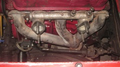
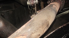
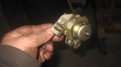
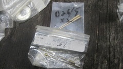
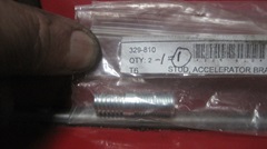
Here's an interesting bit of history. We just removed the old Moss Motors heater valve because it was 3 years old and navigator said there was a puddle of coolant on the floor last week. For the past several years these Moss valves have been failing in slightly less than 2 years average due to the rubber diaphragm dissolving when exposed to glycol coolant, so we are happy to toss this one in the dust bin. At least this time it is not a roadside repair. -- Then installing the heat shield, and it was time to clean the carburetors before installation. We needed to change the fuel metering needles from #6 (for 1600 engine) to #5 or MB (for the 18G engine) depending on if we install a PCV valve or not. S/F sold me 5's, so we'll go with that for now.
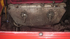
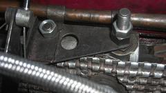
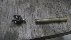
We took this opportunity to change out an incorrect threaded stud holding the throttle and choke cables bracket on the intake manifold. One fell out and was lost a year and a half ago, and we didn't have a spare at the time,so we substituted a longer carburetor mounting stud with a large hex nut for a spacer. Now we do have spares, and we get to fix it properly. I should get that picture later. And put another one of those on the shopping list for a spare part. -- Then we found a failed main jet where the choke clevis was very loose from the jet, and it had to be dripping fuel. I thought the parts were riveted together, but it turned out to be a threaded screw connection, so all it needed was a drop of thread adhesive and screw it back together.
We finally got the needles replaced, and fixed a couple of missing clevis pins, and did some rudimentary cleaning of the carbs without disassembly. I was starting to install the rear carb when navigator reminded me that we had not finished tightening the manifold bolts. Oops. One step back, remove heat shields, tighten manifold bolts, and then reinstall the carbs (promise photo later). We installed a new heater valve, one from Scarborough Faire this time, hoping for longer service life.
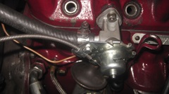
Beginning to see the light at the end of the tunnel here, we got our nice cell core radiator installed,m with new hoses. There is a comparison with the old irregular and soft short life Moss Hoses with new silicone hoses from ... I don't remember where, maybe Scarborough Faire. The silicone hoses certainly look like they will last forever, but they are rather stiff. I cut 1/4" off both ends, which sees to help with installation. I hope they don't transmit too much vibration from engine to radiator.

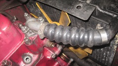
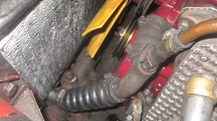
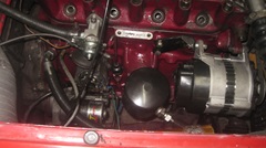 The two of us were about "done in", but figured the alternator would only be three bolts, so go for it. I swear the space between engine and radiator is getting smaller every year, and more difficult to service the alternator. One of us holding a pry bar to snug up the belt while the other makes like a contortionist to tighten the lower bolts in front. Man, I gotta redesign that mounting to make it easier. We finally got it licked before deciding to call it a night. Getting very close now, just needing the spark plugs, distributor cap and coolant fill before first start. But I have to order some parts tomorrow.
Wednesday - November 27, 2024:
First business today was to put together a parts order including a set of short pushrods to replace the ones we borrowed from the Datsun, and a few other odd parts to replenish inventory. Got a phone call from a friend just wanting to chat, killing a half hour that we didn't have to spare. By the time the parts order was called in, the vendor was closing shop at 1-PM, so the new parts will ship on Monday. That's only one working day later including the long Thanksgiving holiday weekend. With luck those parts may arrive Tuesday.
 More time at the computer processing photos from yesterday, updating inventory data for parts recently used, and a few more added to the wish list for future order. I did get the pictures posted to the web page before falling out of my chair, but didn't finish the dialog yet. And didn't get to touch the car all day. Zzzzz, More time at the computer processing photos from yesterday, updating inventory data for parts recently used, and a few more added to the wish list for future order. I did get the pictures posted to the web page before falling out of my chair, but didn't finish the dialog yet. And didn't get to touch the car all day. Zzzzz,
Thursday - November 28, 2024:
Happy thanksgiving. Finally finished the dialog to go with the pictures above, and we're getting to the garage by mid day with great anticipation. Wish us luck.
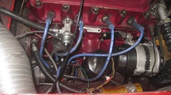
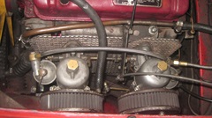
Not long to install spark plugs, distributor cap and wires, plug in the alternator connector, and screw in the temperature sensor. and there are the pictures of both sides of the engine bay fully assembled. Been here before, and we don't trust anything. So, I'll fill the coolant while you watch underneath to see if anything leaks. Oops, stop. It was pissing out almost immediately with puddle on the floor. Damn, pretty sure we did everything right.

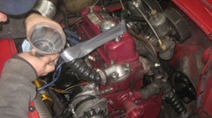
Okay, you fill a little more coolant while I look so see where it might be leaking. It appears to leak at bottom of the water pump, maybe the gasket joint, difficult sight lines. Need to drain it and remove the radiator, fan and pump pulley for better visibility. Then tape over bottom and of the lower radiator hose, and tape the upper hose in vertical position where it can be filled for gravity feed. Then pour in more coolant and watch it run out, sure enough at bottom of the pump gasket joint. Okay, remove the alternator and water pump for a look at the cavity behind the pump at the bottom of the pump flange

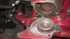
What we found is a notch or divot at the very bottom of he aperture extending to the bottom of the pump flange where the gasket has no wall to seal against. Picture at center below shows the pump gasket in place with a small screwdriver inserted into that notch. The only way the MGA water pump could work in this 18G block is if we fill in that divot to provide a wall for the gasket seal. I will take a shot at this with some epoxy filler. Cut a thin piece of plastic from a AA battery retail pack( slightly thicker than bubble pack), and tape it in place with top edge where we want the wall for height of the filler plug. (Sorry about out of focus).
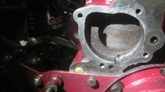
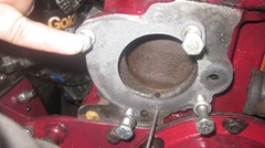
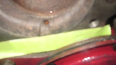
Mix up a wad of JB Kwick Weld to fill the cavity, then get away from it for 4 to 6 hours curing time. Can't wait for the comments on remodeling an iron engine block with epoxy plastic. Check back later.
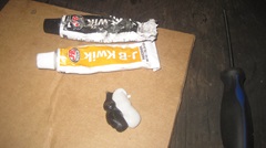
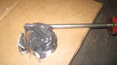
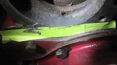
Six hour lunch break for the epoxy to cure, 3 to 9 pm, when I managed to process the photos and notes above. Then back to the water pump problem. Peel off the masking tape, and the plastic card pops right off, no stick. There was a very slight bulge in the epoxy plug where the plastic card was not perfectly flat when taped. I cut a short stick with perfectly flat end on a table saw, wrapped a piece of 220-grit emery paper around it, and carefully sanded the epoxy plug flush to the engine block face.
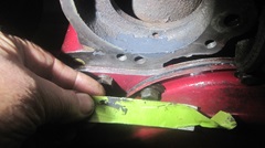
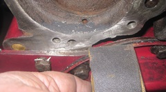
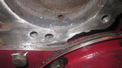
Reinstall MGA water pump with gasket, and reattach the lower hose with bottom end still blocked. Fill coolant into top hose until it is full up for gravity feed, and check water pump gasket joint, no leak. Score one for the good guys. Reinstall alternator, pump pulley, fan and belt properly tensioned. Reinstall radiator and hoses, and top up coolant. Apply the cooling system pressure tester. 10-psi please. Still no leak. Going to let that set for a while.
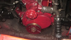
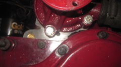
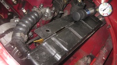
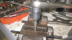
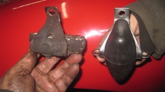
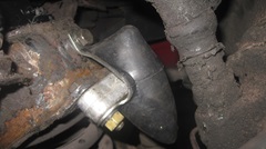
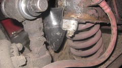
While waiting for he pressure test, we were going to install new rubber buffers for front suspension. Removing front wheels reminded me that we have some lug nuts that drag , may be galling in the threads, and this seemed like a good time to fix them. We took all of the lug nuts to the work bench, clamped a thread cutting tap in the vice, and proceeded to run the threads s in the lug nuts one by one, some of them more than one pass. When finished all of the lug nuts would spin freely on the wheel studs. There was one stud on the right front wheel hub that still had a hitch in its git-along, so we ran a thread cutting die down that one a couple times until the lug nut would spin freely there as well. -- Then on to replacing the front suspension buffers. Oh, the humanity of it all. Since the shock absorbers had been leaking oil for long time (before recent replacement), there was lots of oil and road dust mud caked on the chassis. So lots of time cleaning some of that off while removing the broken buffers and installing new ones.
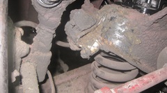

Finally got the new front buffers installed, put the wheels on the car, and got it off the stands back to the floor.
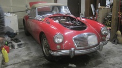
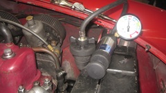 The cooling system pressure test was still sitting in the 10-psi range, so definitely no leaks. Put the tester away, and put the radiator cap on. By then it was 2-am, and we were both frazzled, so we weren't going to fire it up until we got some sleep. Good night all.
Friday - November 29, 2024:
Sleep in for a change, have a good breakfast, get back to the garage by mid afternoon. Okay, just do it. Switch on., pull the choke and pull the Start button. Reluctant to start immediately, we advanced the ignition timing a bit, and then it fired right up. Kick it up to 2500 rpm for 20 minutes for cam and tappets run-in. While waiting for that, we tweaked the timing a little, checked oil pressure and coolant temperature, and smiled a lot. After 20 minutes, set idle speed back to 1000 rpm tweak the timing a bit, check/adjust fuel mixture, reset idle to 100o rpm, and shut it down, top up the oil, reinstall the bonnet.
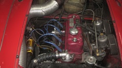
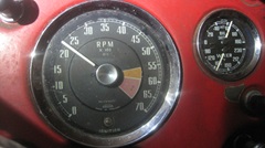

I wanted to do a compression test, just out of curiosity, to investigate and record how goes a freshly rebuilt engine before and after a good break in period. The numbers were:
110 - 95 - 85 - 115 (kind of low as expected).
Then we put about 1/2-oz of oil in each cylinder and did the compression test again.
165 - 135 - 120 - 170, all substantially higher (as expected).
Thinking we may have put too much oil in the cylinders, possibly reducing chamber volume a bit to produce higher numbers, and maybe some of the oil may have been spit out during crank testing, we did a third test on the two higher cylinders.
#1 = 150, #4 = 160 (both down a little (so maybe I was right).
All good enough for a new engine with honed cylinder walls and new rings not yet run in and bedded. We will test again after 500 miles break-in. Meanwhile, one quick trip around the block with a couple acceleration tests in short blocks. A little stutter on acceleration from low speed, pulls strong at higher engine speed, and it idles well, all in freezing weather. Of course it stopped turning quickly after key off, being a still tight new engine. Smile again, pat the car on the bustle, and put it to bed for the night.
Saturday - November 30, 2024:
Updating parts inventory and MGA service list. Catching up a two week backlog of BBS and email. Also a food run to the store to re-stock the larder. Thinking about ordering an early MGB water pump, but not going to do that until I know how long it is. So I posted the question to the MGA forum, and the early MGB water pump is 3/8-in longer than the MGA pump. No-go. Would have to move the radiator forward 3/8-in, and the belt would be misaligned.
 Now I have another idea. Grab a piece of sheet metal, maybe 14-gauge (0.075 thick) like the MGA body steel. Use an MGB water pump gasket as template to cut a sheet steel blank matching the perimeter of the MGB pump flange and the four bolt holes. Use an MGA water pump gasket as template to cut a center aperture in the blank matching the MGA gasket. Bolt the MGA pump to the MGB block with this plate in between, with MGB gasket behind and MGA gasket in front. The thin plate should be strong enough to hold the B gasket down with the small overhang distance at the bottom edge. Likely the fan belt won't mind being misaligned about 0.085-in. And if clearance space between fan and radiator core is an issue, then shim the radiator forward a bit. -- I feel like I must be reinventing the wheel. Surely this issue must have been solved a hundred times over by now. Now I have another idea. Grab a piece of sheet metal, maybe 14-gauge (0.075 thick) like the MGA body steel. Use an MGB water pump gasket as template to cut a sheet steel blank matching the perimeter of the MGB pump flange and the four bolt holes. Use an MGA water pump gasket as template to cut a center aperture in the blank matching the MGA gasket. Bolt the MGA pump to the MGB block with this plate in between, with MGB gasket behind and MGA gasket in front. The thin plate should be strong enough to hold the B gasket down with the small overhang distance at the bottom edge. Likely the fan belt won't mind being misaligned about 0.085-in. And if clearance space between fan and radiator core is an issue, then shim the radiator forward a bit. -- I feel like I must be reinventing the wheel. Surely this issue must have been solved a hundred times over by now.
|