The MGA With An Attitude
FRONT SUSPENSION REBUILD -- FS-202A
 FS-202A - Disassembly (you are here)
FS-202B - Inspection
FS-202C - Swivel Links and Bushings
FS-202D - A-arm Bushings
FS-202E - Reassembly
Disassembly
This procedure will refer to some details on other pages. Start by loosening wheel bolts (steel wheels), lift chassis and set frame on jack stands, loosen knockoff (wire wheels), remove wheels.
Raise front of car, place frame on jack stands, remove road wheels.
Disconnect tie rod end ball joint (or unbolt steering arm on MGB).
Disconnect brake hose and lower pipe (drum brakes) or dismount caliper (disk brakes).
Remove brake drum (drum brakes).
Disassemble brake shoes if desired (drum brakes).
Remove bearing spindle nut and remove bearing hub (including brake disc).
Remove brake backing plate (drum brakes) or dust shield if fitted (disc brakes).
Disconnect anti-sway-bar link (if fitted).
Jack under A-arm and remove top trunnion bolt.
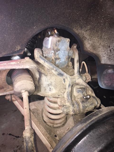
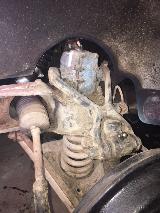
 Place a floor jack under the suspension A-arm, directly under the coil spring. Lift just enough to raise the shock absorber arm free of the rubber bumper. This will unload all of the suspension joints, except the lower A-arm inner pivot and coil spring. At this point you can remove the shock absorber if needed. If all you were after was to replace the shock absorber, you can skip most of the steps above, just jack up the A-arm and remove the shock absorber. If you are disassembling everything, then it is easier to do the steps above while the shock absorber arm is still connected.
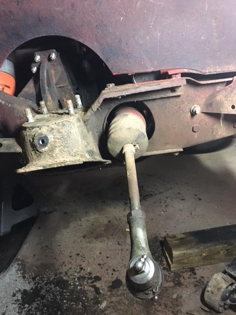
Remove bottom trunnion bolt to dismount swivel pin assembly (or MGB kingpin).
Lower jack and remove the coil spring - (See details).
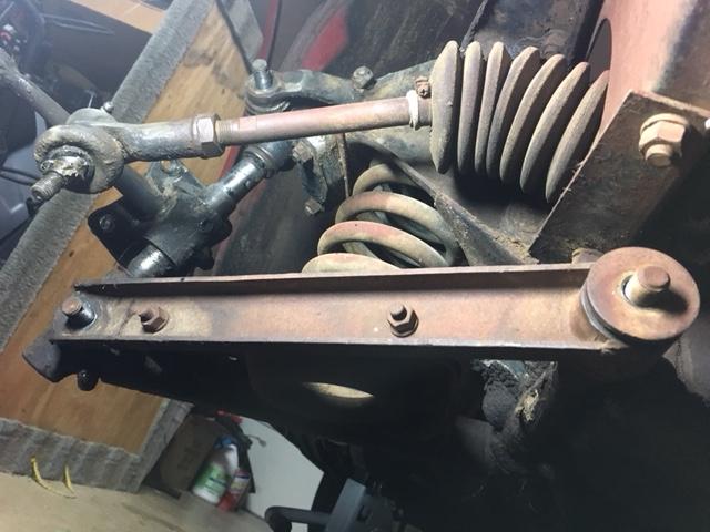
Disassemble lower A-arm brackets (at least one).
Remove A-arm parts from inner pivot shaft.
Remove inboard Pivot from frame (if desired).
Remove coil spring upper alignment spigot (if desired).
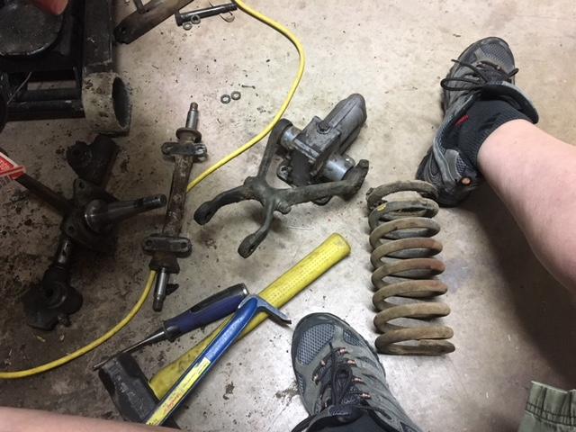
Disassemble swivel pin assembly.
Check to see if swivel pin is straight.
Straighten swivel pin (or replace) if necessary (very unlikely).
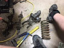
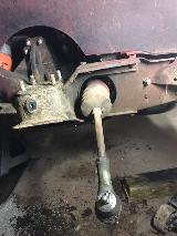 If the trunnion bolts and distance tubes are completely fused and won't budge, start by removing the nuts. Break the bolts if you have to, or use a nut splitter to break the nut. Grind the heads off of the bolts. You can also grind off the tip end of the bolt and the nut if you don't have a nut splitter. Then remove the front side A-arm bracket (one big nut at inboard end plus two small bolts in the spring pan). Pry the lower trunnion away from the other A-arm bracket, then lower the jack to unload the coil spring and pull out the spring. On top you cam remove one arm from the shock absorber, then separate the trunnion from the other shock arm. This leaves the swivel pin assembly with trunnions and frozen bolts free to take to the work bench.
The bolts and distance tubes must be removed from the trunnion before unscrewing the swivel link from the swivel pin. The only thing holding the distance tube into the swivel link is dry hard hardened grease. It should come apart with a big enough hammer. Otherwise heat the trunnion with a torch to hopefully soften the dried grease enough to allow removal of the distance tube.
Aside from the bolt you destroy, the distance tube will most likely also be corroded on the bearing surface, so plan on tossing those into the trash as well. New bolts and distance tubes and sleeve bearings should be included in the suspension rebuild kit.
To disassemble swivel pin assembly, first remove steel bearing tubes from the swivel links, and then unscrew swivel links from the swivel pin. If the steel tube is not removed the links will not come off, or it my bind severely and damage edge of threads from interference of steel tube. Do not disassemble the MGA steering arm and swivel pin from the knuckle unless one of these parts must be replaced. A swivel pin may sometimes be bent from a heavy impact on a tire. If so, then replace it or straighten it before going on.
To remove the sleeve bearing, use a hacksaw to cut through the bushing wall from the inside, after which it should tap out easily. You might wail on the old bearing with a large hammer and punch for removal, but do not hammer on the end of the new bearing for installation. The new sleeve bearing can be pressed in using a large bench vice.
The sleeve bearing is bi-metal with bronze inside of a steel liner. There is a hole in one side that has to be lined up to clear the swivel pin thread when the swivel link is screwed onto the swivel pin. After the sleeve bearing is pressed into the swivel link it has to be reamed to 0.7500 inch diameter. The distance tube will be 0.748 inch diameter to be slip fit with clearance for grease. The distance tube must also be a few thousandths of an inch longer than the trunnion and sleeve bearing so the tube can be pinched tight on the ends in assembly and the trunnion can rotate on the tube.
|