The MGA With An Attitude
FRONT SUSPENSION REBUILD -- FS-202E
FS-202A - Disassembly
FS-202B - Inspection
FS-202C - Swivel Links and Bushings
FS-202D - A-arm Bushings
FS-202E - Reassembly (you are here)
Reassembly
Reassemble everything.
Assemble coil spring upper alignment spigot (if it was removed)
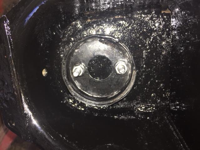
Assemble rebound buffer and spacer block.
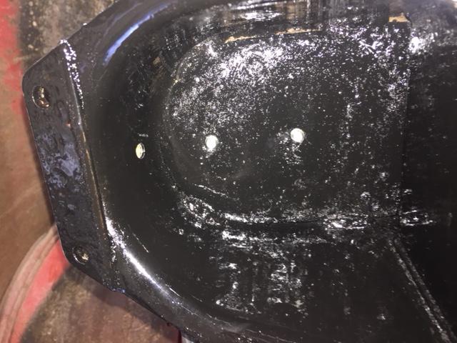
Install shock absorber on frame.
A-arm Pivot and brackets, spring pan and coil spring.
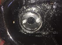
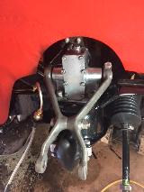
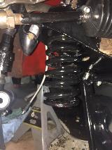
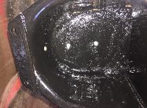 Reassembly is reverse of disassembly, with a little more fiddling. Start by installing the coil spring upper spigot (if it was removed). Install the shock absorber and the rebound buffer and spacer block below the shock arm.
Install rubber bushings at inner ends of the A-arm brackets. Original type rubber bushings or urethane bushings can be pushed into place by hand. Urethane bushings may call for some lubricant for the inner bore to shaft joint (or maybe not). Some people say these parts might squeak in operation, but I have not found that to be so even when running dry. Urethane bushings might last indefinitely without wearing out, where standard rubber bushings might need replacing as often as every two years if you drive a lot. Urethane may give slightly more "feedback" from road bumps, but I happen to like the slightly firmer feel of the suspension. MGB GT V8 style bushings can be wet with soapy water and pushed into place using the bench vice, after which they should stay secure and never move. They may also last a long time without wearing out, because they twist the rubber a bit in operation rather than turning on either ID or OD.
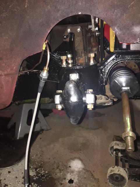
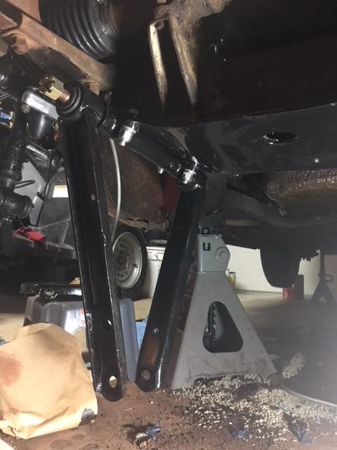
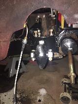
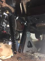
 Assemble the Pivot and A-arm brackets and spring pan on the chassis. Tighten the Pivot to frame bolts, but leave the end nuts and A-arm bracket bolts loose until later. For the MGB GT V8 type bushings it is a good idea to put anti-seize compound on the Pivot to make later removal of the steel lined bushings easier.
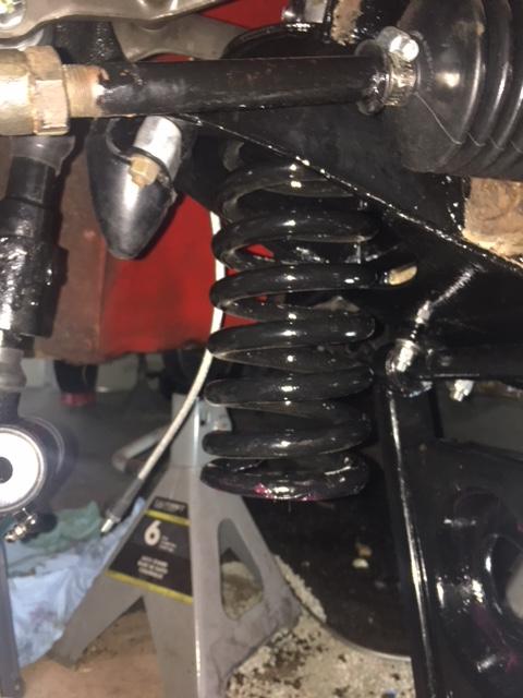
 Insert the coil spring and jack up the spring pan. Loosen the pinch bolt located half way out on the shock absorber lever arm so you may be able to spread the arms slightly when installing the upper trunnion. Insert the coil spring and jack up the spring pan. Loosen the pinch bolt located half way out on the shock absorber lever arm so you may be able to spread the arms slightly when installing the upper trunnion.
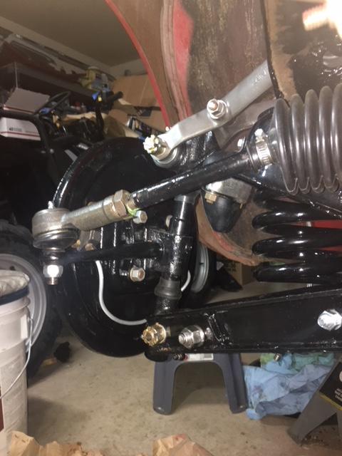
Assemble and install swivel pin assembly.
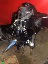
Swivel pins and swivel links have left hand threads for left side parts and right hand threads for right side parts. Top swivel links have the bump stops. Steering arms point forward and swivel pins tilt inward at top. Be sure the threads run free for full length of engagement. Grease threads a bit before assembly.
 Install the swivel link seals. The Swivel Pin seals should stretch to fit tight on the Swivel Link and turn on the Swivel Pin. The Swivel Link (trunnion) seals should stretch to fit tight on the Link Seal Support and turn on the Swivel Link.
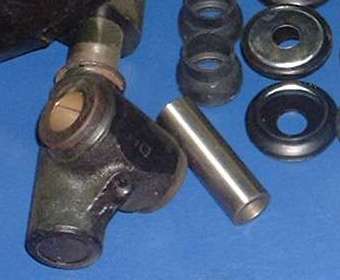
Install swivel pin seal on the swivel link and screw it fully onto the swivel pin. Back off the thread a few turns until the bushing bore aligns with necked down area on the swivel pin. Insert the steel bearing tube into the bushing. Rotate the swivel link right and left as much as two turns each direction to determine where the steel tube will (gently) interfere with the thread on the swivel pin. Count the turns between maximum and minimum engagement where it binds. Turn the swivel link to be half way between these points. Then turn the swivel up to one half turn maximum (closest direction) to align it for assembly to the mating suspension arm.
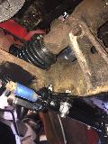
The trunnion seal support has a flanged cup shape. The flat faces the nut or bolt head while the flanged side faces the swivel link. Put the trunnion seal on the support, put the hardened steel thrust washer inside the seal and support, and install the lip of the seal over the end of the swivel link. A small orbital motion can help to make the seal lip jump into position on the swivel link. Repeat for two seals on each swivel link.
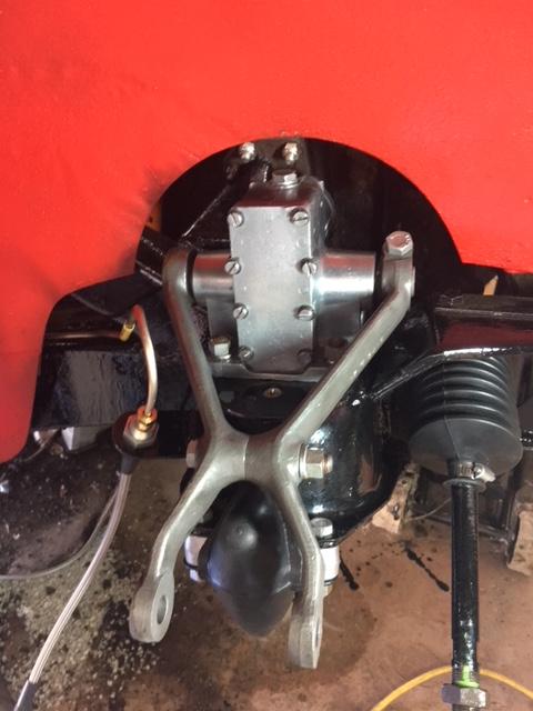
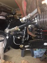 Install the swivel pin assembly onto the suspension arms. Start with the lower trunnion first in case the A-arm brackets may not be in correct alignment. Position the lower trunnion (with washers and seals) between the A-arm brackets. Run an alignment punch or small rod through the holes to align the thrust washers and seal supports with the rest of the bores, and install the lower trunnion bolt. Pull the swivel link assembly into alignment with the shock absorber arm (if A-arm brackets were not yet aligned). Spread the shock arm sides a bit if necessary, and insert the upper trunnion (with washers and seals) into the shock arm. Raise or lower the shock arm as needed, and/or raise the floor jack if necessary, aligning all of the bores with an alignment punch or small rod before installing the top trunnion bolt.
With all bolts still loose, swing the knuckle through a wide sweep, up to 180 degrees, while watching the swivel pin and swivel links. If the swivel pin is straight the swivel links will remain stationary and the swivel pin will appear to stand still as it rotates. If the swivel pin is bent one or both of the swivel links will do a little rocking motion as the knuckle swings around, which is not acceptable. A bent swivel pin could make the trunnion parts wobble in operation causing the bolts to work loose and parts to wear when they should not. Do not settle for less than a perfectly straight swivel pin.
Connect the anti-sway-bar link (if fitted).
Tighten all bolts (except inner A-arm pivot nuts).
Connect the tie rod end ball joint.
Install Brake backing plate (drum brakes) or dust shield if fitted (disc brakes).
Reassemble wheel bearings and brake parts.
Install road wheels and set car on ground.
Settle front suspension and tighten inner A-arm pivot nuts.
Check/adjust front end alignment.
When you are sure the swivel pin is straight and everything is in place you can connect the anti-sway-bar link and tighten all of the bolts. If you use the MGB GT V8 bushings, then leave the nuts on the ends of the A-arm Pivot loose until later. Connect the steering tie rod ends securely. Install brake backing plates or dust shield as fitted. Install hubs with wheel bearings and seals and grease covers. Assemble brake parts, rotors, calipers, drums etc. Connect hydraulic pipes and hoses, and adjust and bleed the brakes. Install road wheels, remove jack stands and lower the car to ground.
Bounce the car a little to settle the suspension to normal ride height before tightening the nuts on the A-arm inner pivots. This step is to centralize the bushings on the A-arm pivot so they will encounter equal twist with both up and down travel of suspension, not over stressing the rubber. Check and/or adjust front end alignment as necessary. A test drive is a good idea to be sure it all works right before you drive too far.
|