The MGA With An Attitude
Body Sill Replacement - RT-612
Making Curved Flanges - (B-Post)
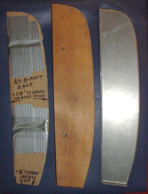
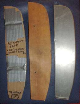 Here I have formed the rear plates for the B-pillars. These start with a cardboard template copied from the car body after outer panels were removed but before any cutting was done on the inner body (see top of page 5). In this case the cardboard template serves two purposes. For the first use, the template shape is traced onto sheet metal, adding margin to allow material for flanges where required. The metal blank can be cut out using the hand held sheet metal shear (or other available tool). Notch the corners where appropriate. Hammer the bank flat if necessary, and trim or de-burr edges if you like.
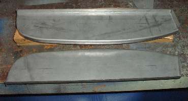
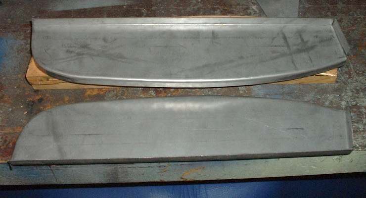
For the rear panel of the B-pillar the inboard flange is straight and square to sit against the flat slab side of the inner body. I made this long straight flange first in the 18 inch bending brake. My cheap bending brake is a bit weak when handling full width material, so I improvise. I slip a scrap of sheet metal a few inches wide in between the brake flange and the edge of the sheet metal part. Then I do the bending a little at a time as I keep moving the sheet metal shim piece back and forth along the length of the brake. This forms the flange just a few inches at a time with much less force required on the brake. The bend angle will progress only a few degrees at a time, similar to hammer forming but in the end it makes a nice clean 90 degree bend, just takes a while to finish. The shorter end flange is easier. This is formed at 95 degree included angle from the long flange. That is close enough to 90 degrees to allow the first flange to lie at the end of the clamp bar, so the short end flange can be easily formed in a single motion of the bending brake.
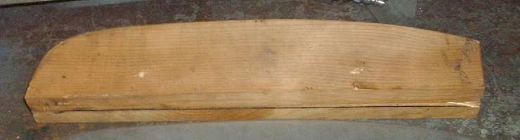
 Then I cut two rectangular 1-inch board blanks (3/4-inch thick cheap pine wood for making only a few pieces). The template shape is traced onto one board, which is placed on top of the second board. I like to drill two 1/4-inch holes and drop in 1/4 x 1-1/2 bolts for temporary alignment pins. The shape is then cut out using a saber saw (or a coping saw or band saw if you have one), leaving a little margin for roughness. I then use a disc sander to clean up and square up the rough edges and finish the block size to the tracing line.
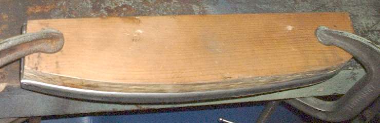
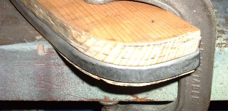
Next place the sheet metal part in between the two wood blocks with the bent flanges of the part firmly against the straight sides of the top block, the top block aligned with the lower one, and the unbent edge of the part exposed along the curved side of the blocks. Lay the assembly over or near the edge of the workbench and clamp it down firmly with two or three heavy C-clamps.
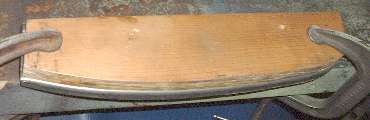 Then I go after it with the blunt end of a ball peen hammer gradually forming the flange downward (hopefully without putting any kinks in it). You may need to loosen the clamps and relocate the assembly a couple of times to have access to the curved end of the part. It could help to work around the end of the work bench with the long curve of the part in front and the short curved end going around the corner of the bench. In that case you may only need to rotate the third (center) C-clamp (not shown here) back and forth to work around it without having to remove it.
When starting this hammer form you can tap fairly gently, allowing the hammer to spring back upward from spring return action of the sheet metal edge. In this manner you can use easy wrist action to control the bounce and rhythm of the hammer. Always keep your eyes on the flange at the point of impact so you see how much the flange moves with each hit and where you are going with the hammer blows. Bend it a little at a time while progressing back and forth along the length of the part to achieve a gradual bend with no sharp kinks.
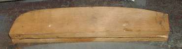
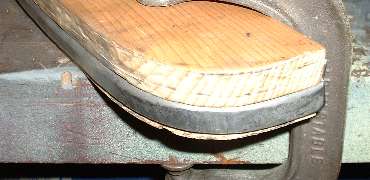 The tricky part here is forming the tighter curve at the end without putting kinks in the flange. You will be shrinking the metal along the tight curve as the flange progress from larger radius to smaller radius. Go slow and gradual with this hammer forming. When you see a wavy edge beginning to appear, do not touch the low point but tap down on the highest point of the wave. If you keep tapping down the highest points of the flange you can force it progressively downward and inward without kinks or ripples, shrinking the metal as you go. The end result is seen in this last picture.
Mind you this metal shrinking requires patience and considerable hammering. It will require more hammer force as it approaches the finished form while being pushed inward to the side of the wood block around the tight radius. It will also require more hammer force on or very near the sharp corner of the bend. As the flange is nearing the final form you can switch to a flat face body hammer to achieve a smoother final surface on the flange. You should expect forming the short radius flange will require considerably more hammering time and effort than the longer curve (which does not require so much shrinking).
There is one last trick to the shape of these parts. The top flange, upward and inboard from the tight curve, is not supposed to be exactly 90 degrees from the face of the panel. The top of the door and top of the outer fender (wing) slope downward to the rear. As such the top of the B-pillar also slopes slightly in the same direction. So as you finish hammer forming the tight radius curve you can think about not hammering it all the way to a full 90 degree bend near the end. If you do form it 90 degrees all the way to the end, it is not difficult to stretch the flange out a little with pliers to match the angle on top of the pillar.
Now you can go back to top of page and have another look a the finished parts. (13 Jan 08)
|