The MGA With An Attitude
REBUILDING THE MG GEARBOX - GT-203F
GT-203A - Test Drive Inspection
GT-203B - Open Inspection
GT-203C - Disassembly, External
GT-203D - Disassembly , Internal
GT-203E - Disassembly, Gear Clusters
GT-203F - Disassembly, Gears and Synchronizers - (you are here)
GT-203G - Reassembly
Disassembly, Gears and Synchronizers
Look at third gear and second gear, on the main shaft immediately behind the input gear (and aft of the 3-4 sliding hub assembly). Grab these gears and try to move them around. There should be little or no motion other than normal rotation. These two gears ride on bronze bushings on the third motion shaft, and there is a bronze thrust washer between these gears. If one gear (or both) feels loose and wobbly, the bronze parts inside will need replacing. These bronze pieces usually do not go bad. When the gear is engaged and driving, it is locked to the shaft and the bushing sees no relative motion. Any other time the gear just idles on the bushing with no load. Towing the car on the rear wheels for long distances could wear out these bushings, as they may (possibly might) then be running with insufficient lubrication (if there is insufficient oil in the gearbox). This particular point is the brunt of another discussion about the gearbox lubrication scheme and towing without disconnecting the drive shaft.
A word of caution here, before disassembling the mainshaft. There are two sliding hubs. One called the Sliding Hub And Dog Assembly (or Sliding Hub Assembly 3rd & 4th Gear) is between the input gear and third gear on the main shaft. In 3-synchro boxes the other is the First Gear & Hub Assembly, the big one with straight teeth farthest back on the main shaft. In the 4-synchro boxes the other is called Sliding Hub Assembly 1st & 2nd gear. These hubs are in two pieces, inner and outer parts with splines in between. When you slide off the outer ring, there are three small steel detent balls with springs behind them. Hold the hub assembly low on a work bench and open very slowly. Maybe place a shop rag over the assembly to catch the little balls and springs when they pop out. If you do not find the little bits immediately, search diligently under the workbench and behind everything - they fly a long ways on their own if you don't catch them. It is of course best not to let them get away in the first place, but this is one item that may take you by surprise even when you're expecting it. These springs should have a nice stiff feel, and the balls should protrude considerably above the surface of the splines when unloaded. When in doubt, the springs are fairly cheap to replace. You might want to buy a couple of springs and a few detent balls before disassembly, as these bits could be really hard to find if they go flying. In most cases, if I know the unit was functioning okay before, I will keep the sliding hubs assembled, assuring that the springs and balls cannot fly free or get lost.

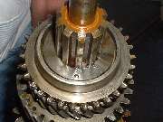 The mainshaft assembly must be substantially disassembled to replace bronze bushings or the 2nd gear synchronizer ring. Start by holding the mainshaft in a bench vice, front end up. Lift off the 4th gear synchro ring, the 3-4 sliding hub assembly, and the 3rd gear synchro ring, then exposing what is seen in the picture here. Click for larger image.
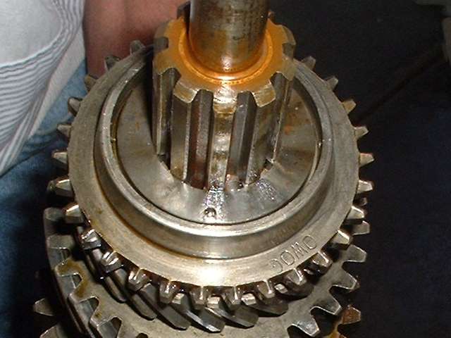
Nestled in a recess in the front face of 3rd gear is a special keyed thrust washer. This has an internal spline cut to match the external spline on the mainshaft. The mainshaft has a circumferential groove slightly wider than the thickness of the thrust washer. The washer is pushed over the spline, and then rotated to move the teeth of the internal spline into the groove in the mainshaft to be locked in behind the teeth of the male spline. The washer has a small hole in the face (seen at the front of this picture) to facilitate rotation of the washer during assembly (or disassembly). In this picture, just to the right of that hole there is a spring loaded pin in a radial hole in the mainshaft, centered in the groove of the male spline. This pin pops up to engage the female spline of the washer to prevent rotation, effectively locking it in place.
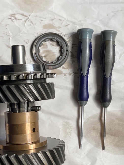
To remove the thrust washer you need to insert a thin blade between the tip of the pin and the root of the spline in the washer. Pry the spring loaded pin progressively inward, depressing it to the root of the male spline on the shaft. Then rotate the washer until the splines are aligned, and pull the gear forward and off the shaft along with the washer. All of this is easier said than done, so your first time may be a little trying, but have patience and you shall prevail. Beware that when you pull the gear off the shaft the spring loaded locking pin my like to go flying across the room to be lost, so hold a hand or a rag beside the gear to catch the pin when it pops out. What you don't see in the picture (rotated out of view) is a small radial hole through the cone flange on the gear. During assembly a pin punch is inserted here to depress the locking pin while the thrust washer is being installed.
This thrust washer was originally available in three thickness (in .002" increments) to adjust end float of 3rd gear. Today a replacement washer might be available only in the thinner of these three numbers. This may be of some concern if you need to replace 3rd gear, where end float is intended to be limited to 0.002" to 0.004". End float might also be increased by wear on the bronze thrust washer between 3rd and 2nd gears. Increased end float of a helical gear increases backlash in the drive train.
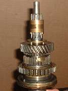
Notice in the picture at right that the sliding 1st gear is pushed back (down) away from the 2nd gear synchro ring (moved into position as though shifted to engage 1st gear). With 3rd gear removed, the bronze bushing and thrust washer (near top) are exposed. These can be pulled off the shaft by pulling forward on 2nd gear. Notice in the picture that there is a hole in the bushing that must be aligned with a radial drill hole in the shaft to admit oil to lubricate the bearing surface. The inside of 3rd gear bushing is keyed to the shaft to fix the orientation of the bushing to assure that the oil hole stays aligned in assembly. The 3rd gear bushing also has castellated ears on the end to lock into the bronze thrust washer, which similarly locks onto the 2nd gear bushing to align that one on the shaft for the same reason, to assure alignment of the oil feed hole for 2nd gear.
Check the thickness of the bronze thrust washer. Parts catalogs may list this part as "interlocking ring". The gears rotating on either side of it bear against most of the side surface of the thrust washer, but not against the tabs which extend inward to key with the bushings. Where the central tabs are not worn you can measure the thickness, and compare that with the thickness farther out to determine the extent of wear on the washer. This wear contributes to end float of 3rd gear at the front steel locking thrust washer. So before you think about looking for a thicker front locking washer, you might consider replacing the center bronze thrust washer.
Measure the OD of the bronze bushings. These should be 1.3115-1.3120" diameter. If the bronze bushings and thrust washer are in good condition they may be returned to service. If any part of the bushing or thrust washer is physically damaged it should be replaced. If the bushings are worn fit new phosphor-bronze bushes (Part Nos. 11G3028 and 11G3029). These were reintroduced at Gearbox No. 24001 to replace the sintered bronze bushings used previously. In reality I have no idea what material is used for currently available replacement parts.
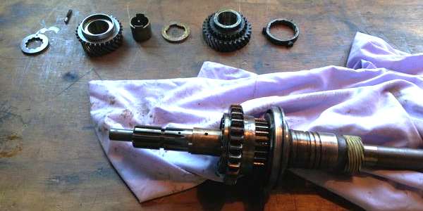
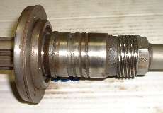
 This picture shows the mainshaft with 2nd gear removed and the 2nd gear bushing exposed. This bushing does not need to be removed to exchange the 2nd gear synchronizer ring. The bushing would need to be removed to pull the 1-2 sliding hub off the shaft. It is good not to disturb
this bushing if it is in serviceable condition. This bushing has a smooth bore and is not keyed to the shaft, with the oil hole alignment being maintained by keying to the 3rd gear bushing through the thrust washer. It is possible to remove 1st gear from the central splined hub (without removing 2nd gear bronze bushing) if you need to inspect or service the ball and spring detents. Between the 2nd gear bushing and the 1-2 fixed hub there is another thrust washer, which you most likely will never need to remove (except to remove the 1-2 fixed hub).
This picture shows the mainshaft with 2nd gear removed and the 2nd gear bushing exposed. This bushing does not need to be removed to exchange the 2nd gear synchronizer ring. The bushing would need to be removed to pull the 1-2 sliding hub off the shaft. It is good not to disturb
this bushing if it is in serviceable condition. This bushing has a smooth bore and is not keyed to the shaft, with the oil hole alignment being maintained by keying to the 3rd gear bushing through the thrust washer. It is possible to remove 1st gear from the central splined hub (without removing 2nd gear bronze bushing) if you need to inspect or service the ball and spring detents. Between the 2nd gear bushing and the 1-2 fixed hub there is another thrust washer, which you most likely will never need to remove (except to remove the 1-2 fixed hub).
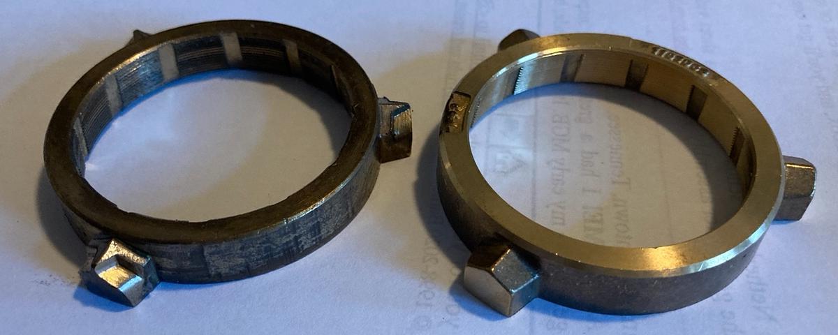
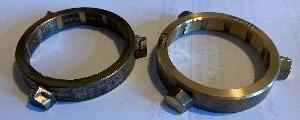 Here we have a picture of a well worn synchronizer ring and a good one. Photo compliments of Dave Davidson. Notice the serious wear on the "roof of the dog house". That much wear makes it pretty much dysfunctional, so hopefully you can get it changed out before it gets that bad.
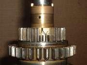
 Beyond the 1-2 sliding hub is a shoulder on the mainshaft, so there is nothing else to be removed from the front. The large ball bearing is positioned against the back side of that shoulder, to be removed or installed from the back end of the shaft. Immediately behind the bearing is the helical grooved oil pump spool (often referred to as "spacer" or "distance piece" in parts lists). Behind that is the speedometer drive gear. For the 1500 type unit the speedo drive gear is retained by a locktab washer and hex nut (seen in this picture). The speedo gear is keyed to the shaft, but the spool is not, so the retaining nut needs to be tight enough to prevent any rotation of the spool on the shaft (so the helical groove oil pump will continue to work).
Remember there are early and mid 1500 gearboxes with different size output splines and different shaft length. The oil pump spool, speedo drive gear, locktab and nut are all slightly different to match the shaft, and are not interchangeable. However, the mainshaft and rear housing can be exchanged as a set to convert from early to mid 1500 model gearbox.
For the 1600 type gearbox the locktab and nut are replaced by a long tube spacer, held in place by the rear ball bearing and output flange and big nut on the back end of the shaft. The oil pump spool and speedo drive gear for the 1600 (and MK-II) type unit are the same as for the mid 1500 unit. Again, the mainshaft and the rear housing can be exchanged as a set for model conversion.
As for the rest of the internal stuff, just be sure that the parts are all there and nothing's broken. The gearbox is not like an engine. No machining is required here, just replace any worn or broken parts and reassemble it. If you have the right parts in hand it can be back together the same day, possibly within a few hours of first cover removal. Taken in small steps and bite size subassemblies, it is simple enough and goes together like tinker toys.
|