The MGA With An Attitude
REBUILDING THE MG GEARBOX - GT-203E
GT-203A - Test Drive Inspection
GT-203B - Open Inspection
GT-203C - Disassembly, External
GT-203D - Disassembly , Internal
GT-203E - Disassembly, Gear Clusters - (you are here)
GT-203F - Disassembly, Gears and Synchronizers
GT-203G - Reassembly
Disassembly, Gear Clusters
For the next few paragraphs you can decide for yourself whether to remove the input shaft or output shaft first. This may depend some on how tight the main bearings are in the housing, or what success you may have with tapping from inside with a long brass drift and a light hammer. I usually remove the input shaft first, as long as I find it possible. The 1500 and 1600 type gearboxes (and some early MK-II units) use the 10-spline input shaft. Later MK-II units (and early MGB) use the 23 spline input shaft. The input shafts are interchangeable (up to and including 1967 model year) if you use the matching clutch disc.
The next part sounds easy enough, but may require a little tact and understanding (pry bar or slide hammer or gentle hammer and big punch). Withdraw the input shaft with bearing and gear from the front. Expect the big ball bearing to be a snug fit in the case, so this may require some encouragement. Keep the shaft and bearing straight during removal to avoid having the bearing jam tight in the housing.
When the input gear comes out, expect a bunch of needle bearing rollers to fall out from the inside. If the assembly is held horizontal, some of the rollers may remain inside the input gear. Many of the rollers will fall into the gear case. A pencil magnet can help with retrieval. Some rollers might fall on the floor if you're not careful. Count carefully, you should have 18 rollers, don't loose them. They are not expensive, but it's a tough grit if you have to wait for delivery of parts because you lost one roller. And don't even think of trying to reassemble it with only 17 rollers. These rollers are usually in good condition. Measure them with a micrometer (.118 inch diameter), and inspect them with a magnifying glass. If they are smooth with mirror finish they are most likely good to re-use. If they have any visible marks in the surface they are good for the trash.
Extract the mainshaft assembly out the back of the case. There is a thick plate ring mount around the ball bearing which should come out with the assembly. This ring carries an anti-rotation dowel pin which engages the rear housing and must be properly aligned during later reassembly. You may (optionally) use a punch or small chisel to mark the relationship of bearing carrier to case, which may make reassembly easier. The bearing carrier will likely be a snug fit in the case and may need encouragement, but
 at least the mainshaft assembly comes out in tact with no loose parts, almost.
From the front end of the mainshaft assembly you can slip off the 4th gear synchro ring, the 3-4 sliding hub assembly, and 3rd gear synchro ring. Do not disassemble the sliding hub assembly unless you have a very good reason (and curiosity is not a very good reason). More about this later. Check the brass synchro rings for wear, particularly on the doghouse shaped ears. In many cases these will not be worn much, and you might re-use the parts. The 3rd and 4th synchro rings are the same part number. If 3rd is worn slightly and 4th hardly at all, you might switch places with them for extended service (like rotating tires for more even wear).
Finally lift out the laygear and thrust washers, retrieve any loose bits you may have dropped in the case, and you should be left with an empty gear case. For the working guts of the unit you now have the input gear (first motion shaft), the laygear (second motion shaft), and the mainshaft assembly (third motion shaft).
Clean the inside of the main gear case and rear housing sometime prior to reassembly. Also plan on degreasing all nuts bolts and washers and check the threads for free running with fingers only prior to reassembly. Threaded parts with "a hitch in the git-along" can be cleaned up with thread chasers. It is best to do this immediately after disassembly so you have no surprises at assembly time. Replace any damaged fasteners.
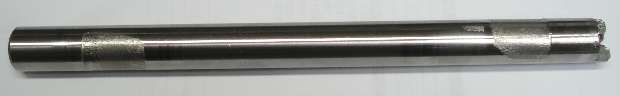
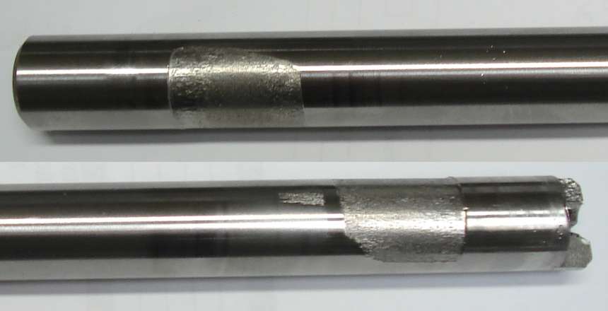
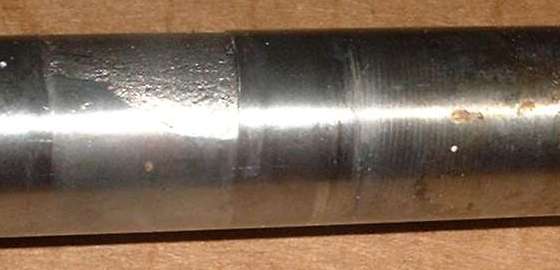
You will likely find the lay shaft to be worn somewhat where the needle bearings run against it. You should probably replace the lay shaft,
 but it's a judgment call when you see it. If it doesn't look too bad, and you drive the car in a civil manner (yeah, sure), you may opt to put the original back in. But personally, I thrash the crap out of the thing, and I expect to keep it another thirty years, so I figure a new lay shaft and needle bearings to be a good investment. They're not the most expensive parts in there, and I've done it for multiple gearboxes now, some of which had done enough miles to have the layshaft worn and replaced twice.
The greatest layshaft shaft wear occurs at the smaller end of the gear with the single needle bearing. Some people feeling a little crafty here will shorten the tube spacer to allow for installation of one more needle bearing. This will improve the life of the layshaft considerably, so it may be worth considering. This is a nice modification in combination with installing the improved 2nd gear with steel synchro ring. If you do add the 4th needle bearing, it is advisable to also drill another radial hole in the layshaft to feed oil to the new bearing. Yes, they are oil fed through axial holes drilled from the ends of the shaft.
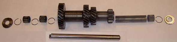
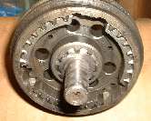
If the layshaft looks particularly chewed up (which is fairly common) then it's a good idea to also replace the needle bearings inside the laygear. Parts in the picture above are used to mount the laygear on the layshaft. From left to right they are: front thrust washer, circlip, needle bearing, circlip, needle bearing, (laygear), spacer tube, needle bearing, circlip, and rear thrust washer. Original needle bearings may have loose rollers and separate end caps. Replacement needle bearings will most likely be one piece assemblies with the rollers held in assembly by a thin cage. See more pictures and notes under Layshaft improvements
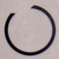
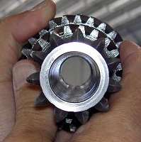 To remove the needle bearings from the laygear you have to extract a circlip from each end of the gear (remove 2 only). The 2nd clip in from the large end of the gear can be left in place. The circlips are a little tricky to remove. They have angled ends, so you can insert a narrow screwdriver blade between the ends and twist to raise one end of the ring. Then slip a second thin blade under the ring to keep it out of the groove. Using two thin blades, work your way around the ring to lift it out of the groove all the way around. This will quite likely permanently distort the ring, damaging it beyond use, so plan on replacing these circlips any time you remove them. Luckily they are easier to install than to remove.
There is a much easier way to remove the circlips. The only reason for removing the clips is to replace the bearings, so we presume the old bearings will not be re-used. Place a small punch against the clip half way around from the tips, and give it a whack with a hammer to break the clip.
If you have to replace the laygear for any reason you should check and/or adjust the end play for the laygear. With the laygear mounted in the housing, nudge it fore and aft a bit and measure the motion in that direction. It should be a small amount, in the order of 0.002" to 0.006". If it needs adjusting it is done by exchanging the rear thrust washer for another of a slightly different thickness.
You may also consider replacing the big ball bearing on the input shaft. It's a pretty rugged part, but it depends a lot on its past history of maintenance and such. It is good to check this bearing while running before you yank the engine. See earlier notes on the test drive. Otherwise find more information on bearing inspection under Universal Tech. When the parts are in your hands, try wiggling the outer bearing race. These big ball bearings do have a small internal clearance, so a little wiggle is okay, as long as it turns smoothly without any noticeable scratching sounds. It should be very smooth to the touch when rotated with a little oil in there. If you find a lot of wobble or nasty noises, it's a goner for sure.
Check the front spigot nose of the mainshaft for wear. This should be 0.5690/0.5685 inch diameter (14.45mm), and smooth with a mirror finish. If the spigot bearing surface is rough or damaged in any way, the mainshaft would need to be replaced. The alternative of welding up and re-grinding the spigot surface is likely cost prohibitive. Also run a wire through the front restrictor orifice or blow air through it to verify that the oil passages all the way back to the oil pump spool are clear.
|