The MGA With An Attitude
Replacement TURN SIGNAL RELAY, 5-year overhaul - TS-202A
As a follow on to the prior page, my converted turn signal relay unit (installed in June 2005) finally had a problem. After more than 5 years in service it began missing a connection for the left turn signal, in July 2010. At first a rare miss, it could be triggered successfully by a second or third actuation of the turn signal switch.
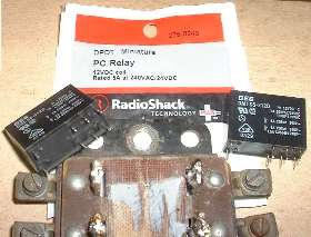
 As usual, intermittent electrical problems can be near impossible to diagnose. I installed a piezoelectric buzzer ($3 from RadioShack) connected to the turn signal indicator lamp as a diagnostic tool. With this I can hear when the turn signal works and when it doesn't.
With time the misfire got more frequent, and left turn signal application could require multiple actuations of the switch. One day when it seemed particularly difficult I pulled the cover off of the relay box and poked around with a test light. I was finally able to recreate the problem.
 It turned out to be a bad relay contact where the COM terminal would not make contact with the NO terminal with flasher power input. If I tapped the relay with a screwdriver it would work. On a chance that it might be a dirty contact, I used a jumper wire to actuate the relay repeatedly through 1000 cycles, hoping it might clean itself. That actually seemed to work, for a while. Then later it was permanently dead.
So far a one time failure, and it did last for 5 years, so I will try it one more time. Off to RadioShack for two more relays. Hard wiring in the same manner is still quicker than installing sockets with 5amp rating, so there I go.
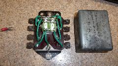
Clip nine wires and tap once with a wood chisel to break the epoxy bond to remove the old relays. Un-solder the old wires and clean epoxy off down to the flat base. Solder nine new 3-inch pig tales to the base terminals. Trim wire ends as necessary to assure two relays will fit between the base terminals.
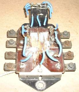
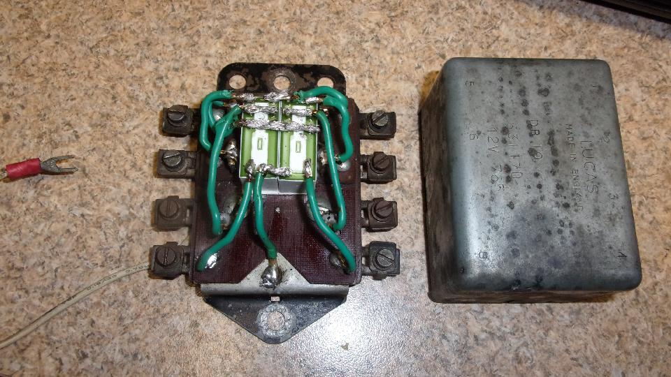
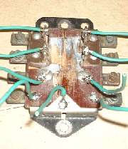
Mix a dab of 5-minute epoxy, stick the relays together and to the base, take a 10- minute break. First wire to connect is power input from the brake switch (terminal 5). Cut pig tale to length, strip appropriate length, twist the wire, poke it over the relay pins on the NO terminals, and solder in place.
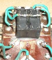
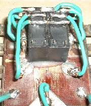
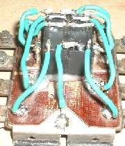
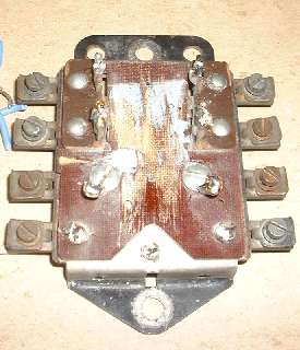
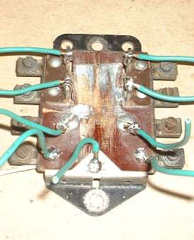
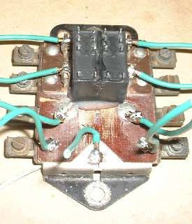
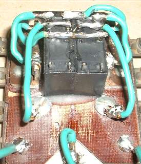
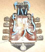
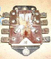
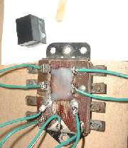
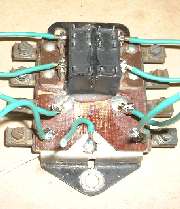
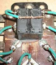
Next (photo above left) is connection for flasher unit (terminal 1) to one NO pin on each relay (top center pins), then left and right front signal lamp outputs (terminals 2 & 6) to the other NO terminal of each relay (top left and right pins). Connect left and right rear brake (and turn signal) lamps (terminals 3 & 7) to the COM terminal on each relay (above center photo). Finally (above right photo) connect the chassis ground wire to one coil terminal on each relay, and connect left and right relay trigger inputs to the remaining coil terminals.
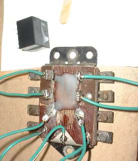
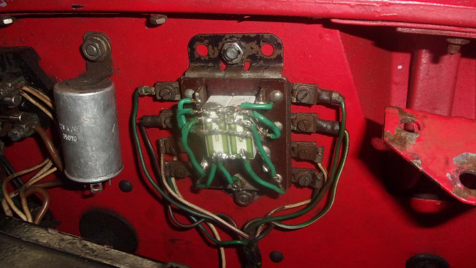
Having done this before, no question it would work, so no bench test needed. Bolt it in the car, connect eight wires, and drive on into the sunset.
Addendum April 2013:
If you were so inclined, higher temperature relays do exist (just not at RadioShack). An example is the Finder 40.52, 8-amp relay with temperature range -40dC to 85dC (-40dF to +185dF).
Addendum July 29, 2020:
Replacing the relays again, 9-1/2 years, 231,544 mi. I think I'll call that acceptable for a daily driven high mileage vintage automobile. I used the higher temperature relays this time (85dC, 185dF). See travel log July 29, 2020. With a little luck, this one should out live me.
Addendum August 24, 2022:

Another relay contact failure, this time with the high temerature relays after 2 years, 30,576 miles. See travel log August 24, 2022. The relays were still clicking, so maybe no difference between high or low temperature units, as they can both burn contacts.
|