The MGA With An Attitude
WIPER MOTOR Armature Rewinding -- ET-217D
This article contributed by Bob Shafto in December, 2021
MGA Lucas Wiper Motor Armature Repair
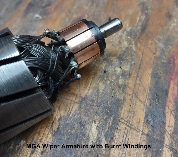
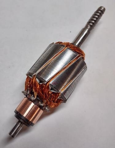
Investigating a MGA wiper motor failure, I found the armature windings were fried. There were a few wires disconnected from the commutator but the main cause was wires rubbing against sharp corners on the armature shorting to ground.

Figure 1 Burnt Armature Windings
|
|
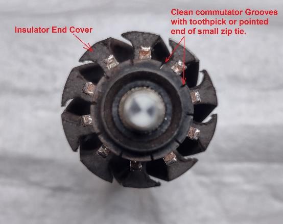
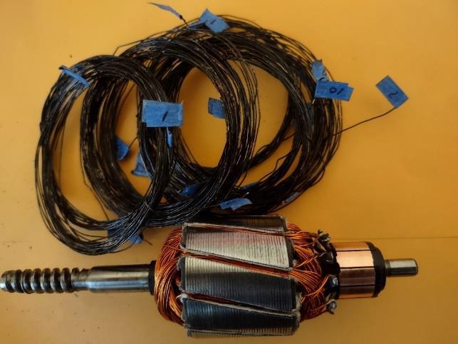
So first step is to remove all the windings and clean the soot left by burnt insolation. Clean the commutators by spinning the armature in a drill or lathe using a folded piece of 400 grit sand paper on the commutator. When the commutator is clean, use or toothpick or pointed end of small tie wrap / zip tie, to clean the grooves between commutator segments.
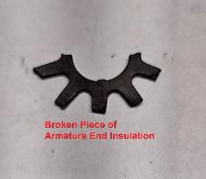
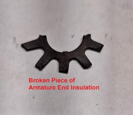
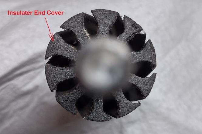
Figure 2 Armature End Insulator
|
Next, inspect the insulating pieces and replace if necessary. Insulation is to prevent the wire from contacting metal especially around sharp corners.
| |
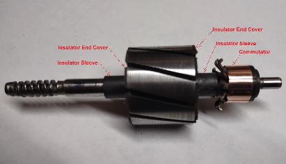
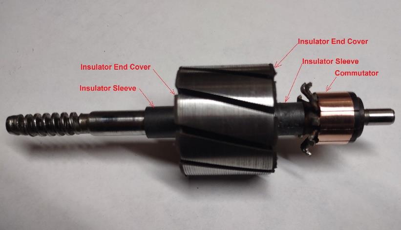
Figure 3 Armature Insulators
|
Insulating material (fish paper) comes in a varity of sizes and shapes.
The improtant thing, is it shold be flexable and able to withstand 230 degrees ferinhite.
The ends are .050 to .060 thick and the slot paper is .010 thick, 1 1/2" long 1 1/8 wide.
For the ends (fig 2), make a hole in the center to fit snugly over the insulator sleeve and glue to the armature face. Then use an X-Acto or similar, to cut the gaps between segments, using the segment as a guide.
The sleeves, usually not damaged but if needed, can be formed by wrapping and gluing insulation paper around the shaft ½ tall and ½ outside diameter.
To replace the insulators on the commutator end, cut them in half then glue them in place from opposite sides.
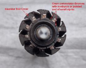
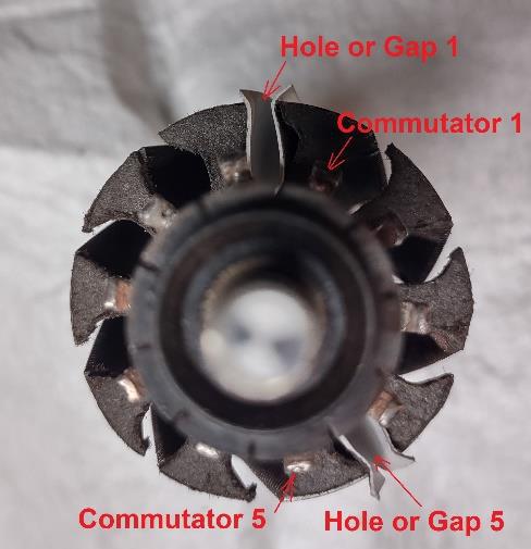
Figure 4 Armature Commutator End
|
| |
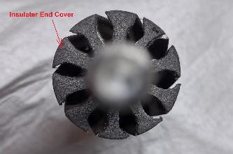
Figure 5 Armature Shaft End
|
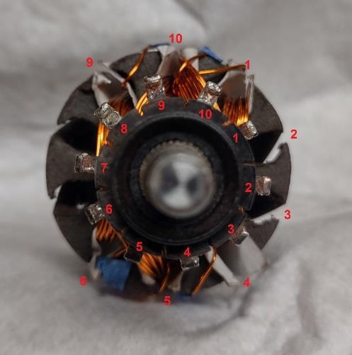
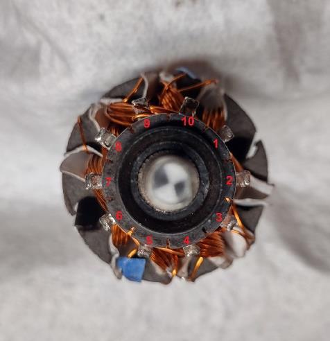
Once the armature is cleaned and insulated, you can begin wrapping the coils.
Begin by numbering the segment openings (holes). You will need a total of about 135 of 24ga coated transformer wire (1lb spool is enough to wrap 6 armatures). The wire is .020 diameter, 0.02567 ohms per ft. Each coil takes 26 wraps and there are 10 coils.
Wire armature in 5 parallel layers. Label each end of each wire. Dont solder ends until all windings are done.
| |
Commutator Start |
Down Hole |
Up Hole |
Wraps or Windings |
Last Wrap Up Hole |
Commutator End |
| Layer 1 |
1 |
1 |
5 |
26 |
10 |
10 |
| Layer 1 |
6 |
6 |
10 |
26 |
5 |
5 |
|
| Layer 2 |
10 |
10 |
4 |
26 |
9 |
9 |
| Layer 2 |
5 |
5 |
9 |
26 |
4 |
4 |
|
| Layer 3 |
9 |
9 |
3 |
26 |
8 |
8 |
| Layer 3 |
4 |
4 |
8 |
26 |
3 |
3 |
|
| Layer 4 |
8 |
8 |
2 |
26 |
7 |
7 |
| Layer 4 |
3 |
3 |
7 |
26 |
2 |
2 |
|
| Layer 5 |
7 |
7 |
1 |
26 |
6 |
6 |
| Layer 5 |
2 |
2 |
6 |
26 |
1 |
1 |
|
Figure 6 MGA Wiper Armature Winding Chart
|
 Start by placing insulator paper into slots 1 and 5.
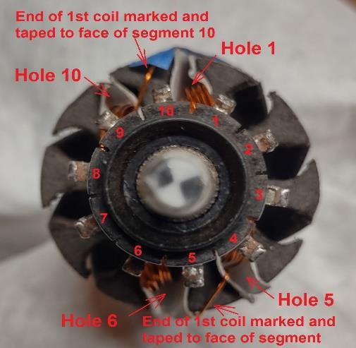
Next, wrap wire around commutator terminal 1 leaving a ½ tail then run the wire down hole 1, across the bottom and up hole 5, across the top and down hole 1 again (this is one wrap). Do this 25 more times, keeping each winding tight. The ends of the paper will fold over the corner on the ends to protect the sharp edges. The 26th wrap will go down hole #1 and up hole #10. Cut this end at the top of the commutator to leave excess for later. Label both ends of the windings and tape them to the face of the armature.
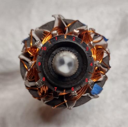
Use the chart above and diagram below to wrap the rest of the coils. See figures 8 14 for visual.
Note: When all the windings are finished, pull the wire pairs that are taped to the armature face, up to the corresponding commutator. Mark the wire where it reaches the commutator terminal and scrape off the insulation varnish coating using an X-Acto knife or similar, Be careful not to damage the wire.
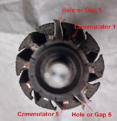
Figure 8 Armature Ready to Wire
|
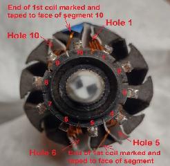
Figure 9 Armature Winding Layer 1
|
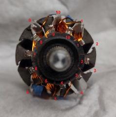
Figure 10 Armature Winding Layer 2
|
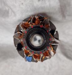
Figure 11 Armature Winding Layer 3
|
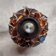
Figure 12 Armature Winding Layer 4
|
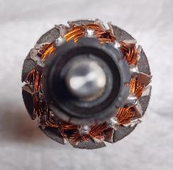
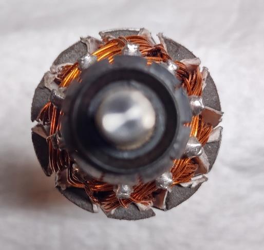
Figure 13 Armature Winding Complete
|

Figure 14 Armature Complete
|
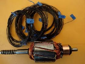
Figure 15 Armature Old and Repaired
|
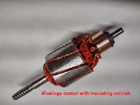
Figure 16 Armature Finished With Insulating Varnish
|
|
Tip - After all the windings are done and soldered to the terminals, liberally coat all the windings with insulating varnish for extra protection. This will help glue them in place and add extra electrical protection. Figure 16
|
|