The MGA With An Attitude
LIGHTING SWITCH Repair - ET-116A
On 1/26/2016, Mark Wellard in Australia wrote:
"I have spent the day repairing my light switch. Rebuilding an original light switch offers the chance to bypass poor reproduction switches when failure occurs. There is some disincentive to attempting this because the nut holding the original switches together is soldered in place. With a soldering iron and solder removing tool or wicking material, this is readily removed and the switch can be repaired/cleaned.
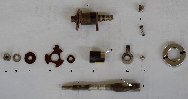
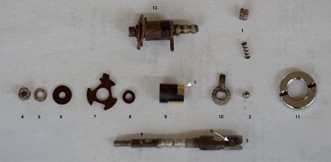
Before dismantling the switch, take out the detent ball and spring (2) by removing the grub screw (1) on the side of the switch body. If you dont do this, there is a chance that the ball will fall through the body of the switch when you remove the shaft (I know
) and disappear.
Remove the switch knob from the shaft by depressing the small pin (3-b) before pulling the knob. It is not necessary to remove the bezel (11).
Once unsoldered, the small nut (4) and two accompanying washers (5, 6) can be removed with needle nosed pliers. [The little hex nut measures 0.215" across flats, and 7/32" socket fits nicely]. Next, remove the asymmetrical fiber end piece (7) and fiber bush that sits inside it (8). Take care as some of the fiber washer material may be brittle with age.
Gentle wriggling of the shaft will allow you to pull it from the front and out of the body, leaving the other two switch components behind. The Bakelite and brass contact (9) rotates on the shaft (located by flats) and is insulated by the fiber washer bearing (8) that allows clearance to the asymmetrical fiber washer end plate (7). The last piece is the washer with locating finger (10) that guides the contacts relative to the body, via the long slot in the body. This may fall out without much help. If necessary, remove these parts with small pliers or tweezers.
There are flat sections on the shaft to locate the internal parts and the guide finger (see discolored area (3-a).
The contacts can be repaired/cleaned as required and reassembly is the reverse procedure, as they say in the manuals. The assembled components are shown at (12) on a broken shaft.
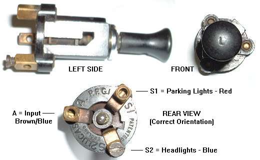
Pay attention to the orientation during assembly. Push the shaft into the body after prior placement of the contacts (9) and the guide finger (10). With the pin of the shaft (3-b) facing down and the slot in the switch body facing towards you, the guide finger will be in the correct position for the knob to be aligned correctly, once in the dash.
The contacts (9) should then be inserted with the longest bass contact facing away from the guide finger and the end with the brass extending to the edge (9-c) towards the threaded end if the shaft. Because of the locating flats, it is easy to align.
Next, replace the fiber bearing (8) and asymmetrical locating piece (9). There is a locating finger on the end plate corresponding to the cut-out in the switch body. The second fiber washer (6), metal washer (5) and the nut can then be assembled. When tightened and after testing the switch function, the nut can be re-soldered. Loctite may work but if the switch gets warm during use, this may weaken the Loctite.
|