The MGA With An Attitude
BROKEN EXHAUST MANIFOLD, Welding #2 - EX-201A
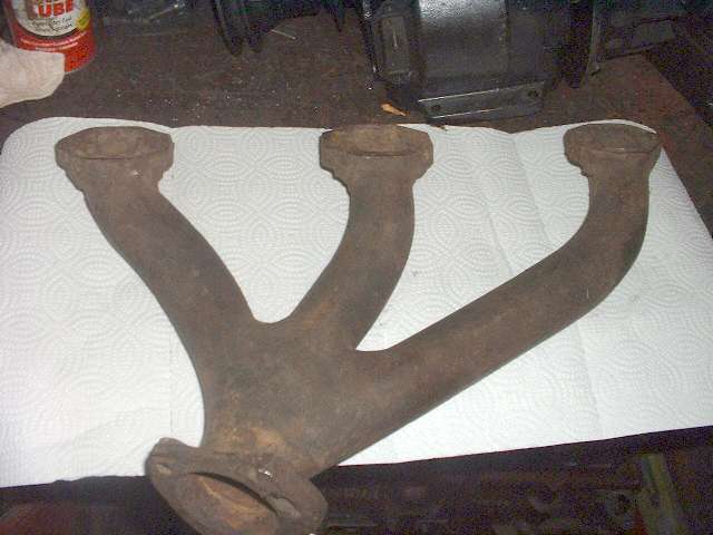
Ah-ha! I have just had the opportunity to weld up another exhaust manifold, and this time I have pictures. This manifold was sort of a basket case. I picked it up at a swap meet for cheap, because it was missing all of the bottom studs, and the threaded holes were damaged. One ear had been welded once before by tacking on a little rectangular bar to one side. It looked like a good weld at first, but when I started to weld up the hole to re-drill it, the old weld had lots of blow holes and slag inclusions. I used a die grinder with a cut-off wheel to cut to the base of all of the imperfections to weld them up solid. Had I known how bad the prior weld was, it might have been easier to cut the ear off and start over. But I was persistent, so it was finally finished.
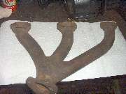
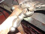
To make a long story short you need to read the prior article on welding an exhaust manifold. My method is nothing exotic, more like re-casting the thing freehand. I heat the damaged area with an acetylene torch until it melts and makes a puddle, then fill in some more metal with any old hunk of iron, like a black iron gas pipe or a rail road spike. Built it up freehand until the area is larger than original size, then let it air cool. Then grind it back to original profile, and finish by drilling and tapping the required holes. This can easily kill a few hours, but if you have time it's sweat equity for your car.
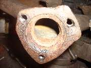
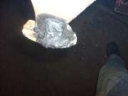
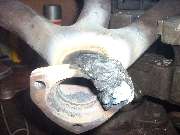
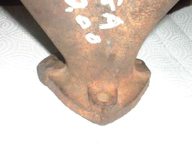
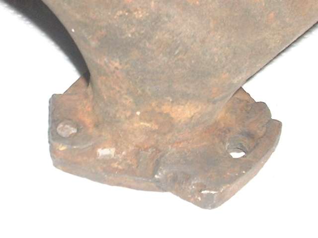
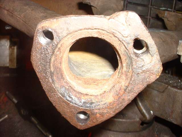
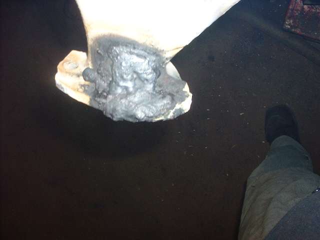
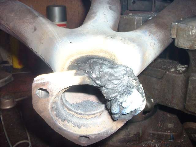
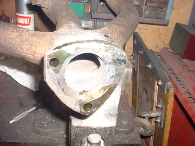
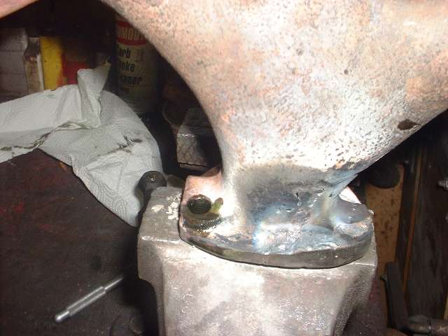
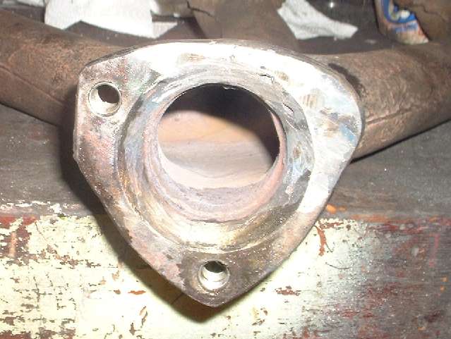
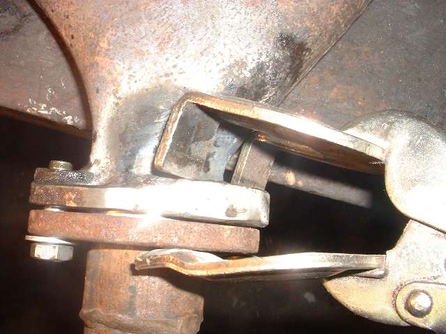
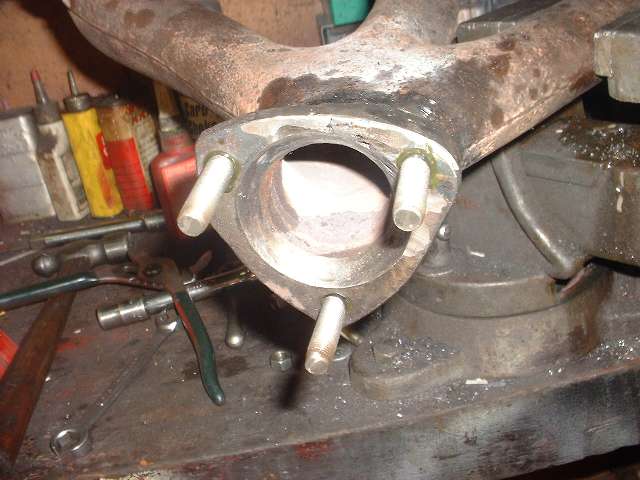
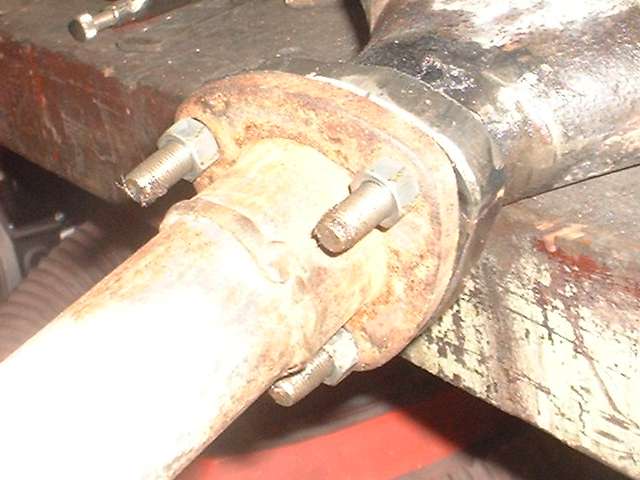
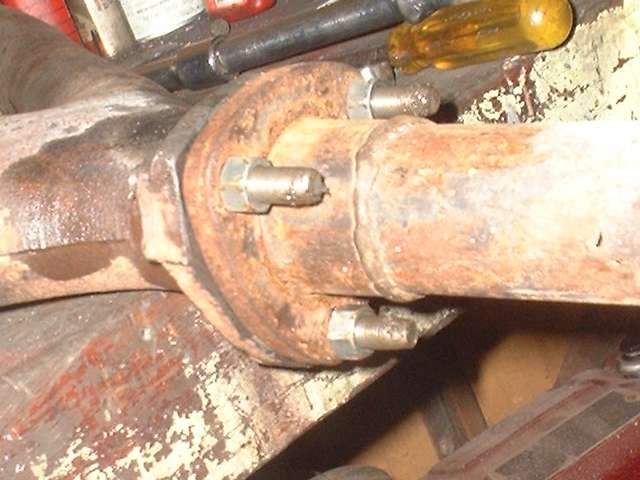
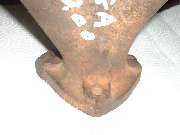
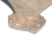
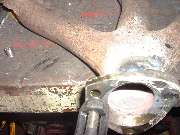
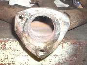
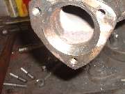
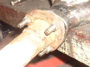
The bottom flange had one hole with a stripped thread, and one hole with a very rusty thread. Both of those could be repaired with Heli-Coils. The third hole had a prior weld repair, and the hole was too large to hold a Heli-Coil, so it would have to be welded shut. The pictures above tell it like it is. The welding (re-casting freehand) is built up to a larger size, really ugly to look at, but structurally sound. After an hour of air cooling time, and nearly another hour of grinding with bench grinder, angle grinder, die grinder, and a sanding flap wheel, the pictures below show what it looks like once it is ground back to original profile. I even cleaned some rust out of the conical seal seat.


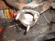
The next move was to install Heli-Coils in the two remaining open holes. That's a pretty simple process. See article UT-105, and pictures below. The greenish stuff in the tapped holes is Loctite adhesive to hold the Heli-Coil once installed.
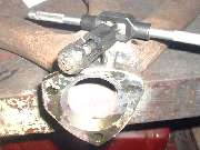
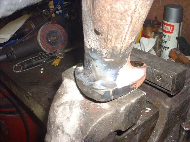
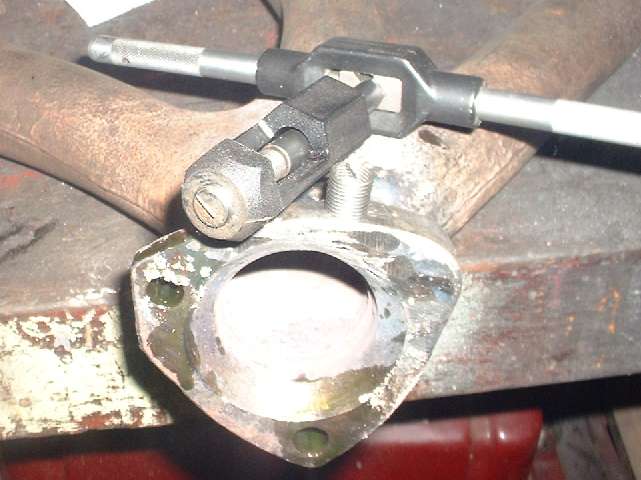
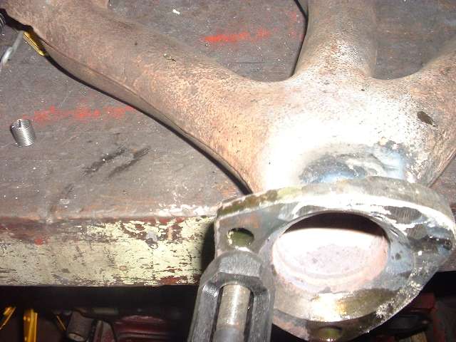
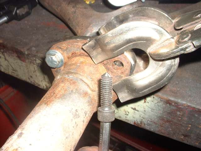
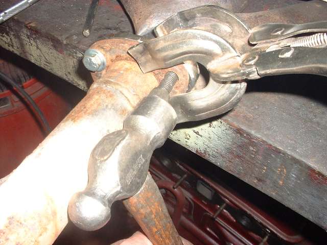
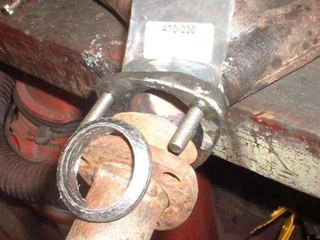
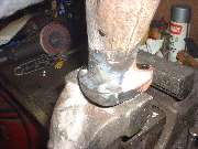
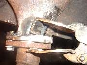
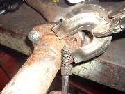
Next I assembled the header flange and ring seal with two bolts and a clamp to find the proper location for the third hole. I ground a conical point on a hardened steel screw to serve as a centering punch. Put that in the open hole, move it around to all extremes, and tap it a few times with a hammer to mark the limits of location. Then disassembled the parts and put a center punch mark in the center of the dimple pattern, and drilled there. I clamped the part in a bench vice and used a hand drill and the small block of a combination square to align the drill bit perpendicular to the surface. You can figure drilling through a weld may be tough going, and you may need to resharpen the drill bits a couple of times in the process. Start with a small pilot drill, then work your way up to tap drill size. Tapping a thread in cast iron is usually pretty easy.
About the time I finished the third hole it dawned on me that I had installed fine threads where they were originally coarse threads. Doh! So then I had to conjure up some studs with fine threads on both ends. That wasn't so bad. I used short cylinder head studs, keeping the fine threaded end, cutting of the coarse threaded end to have a 2-inch long stud with one fine thread. Then I cut a fine thread on the other end for most of the length. I should say that the extra strength head studs are not easy to cut. I used the pedestal grinder for cut-off and grind to finished length, and also ground a shallow taper to get the thread cutting die started. The first one took maybe 15 minutes, the other two ten minutes each. But it makes a nice assembly with strong studs that may last a life time.
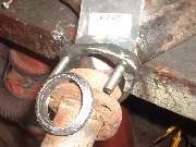
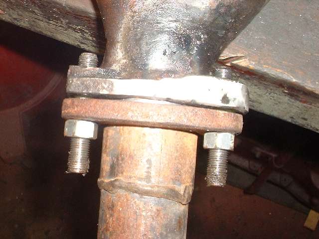
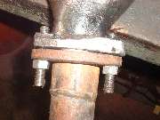
The crowning glory was final assembly when the flange slipped right over the studs with no fuss, as I had taken proper care to assure that the third stud was straight. These studs are long enough to use long brass nuts and lockwashers (as original), or as I prefer, double nut it with stainless steel nuts jammed together so they can't vibrate loose.

Addendum February 2018:
Since the question just came up again, .... Most double threaded studs are coarse thread on the bottom end and fine threads on the top end. This makes it possible to screw the studs in with your fingers, and then torque the nut on to the top end without the stud rotating. This is because the coarse thread has a steeper ramp angle on the thread, causing the nut to turn without the stud rotating. Studs in the bottom end of the MGA exhaust manifold are (normally) 3/8-16-UNC on the short end (in the manifold) and 3/8-24-UNF on the exposed and (for the nut). You can find these studs at a local auto parts store.
That said, the manifold studs in the side of the cylinder head are an exception to the rule. Those are 5/16-24-UNF on both ends (and I have no idea why). Do not expect to find those studs at a local auto parts store.
|