The MGA With An Attitude
MGAguru.com MGAguru.com
FOUR WAY FLASHERS My Way, MGA 1500 - ET-243

If you managed to muddle through the last two articles this one should be a cinch. The way I finally did it is a variation on Flashers The Cheap Way, because I only use one flasher unit, and it could be done without a relay. You might want to print this diagram and keep it on the side while you read the details.
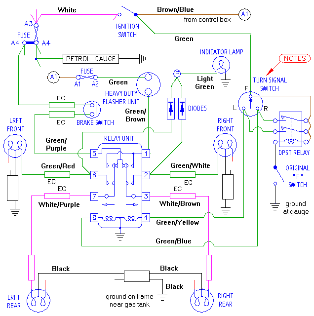
Modified flasher circuit for MGA 1500

Turn signal Switch odd terminal markings My first decision was to use a heavy duty flasher unit, because I tow a trailer a lot and I like the turn signals to flash at the right rate. This will also enable the four way flashers to flash at the right rate, even when they become six way flashers with the trailer in tow. Since I did not readily find a heavy duty flasher unit with a third terminal output for the pilot light, I decided to install a pair of diodes to use the signals from the front corner lamps to operate the dash indicator light. As my MGA does not have fog lights or extra driving lights, the original fog lamp switch has been unused for decades. So I decided to install a very small double pole relay and use the single pole "F" switch for the four way flashers. There just seemed to be bit of charm using "F" for Flashers, and not having to add another switch.

New Materials:
Heavy Duty Flasher - Littlefuse #FLR536/552BP #OFLR536/552P - from K-Mart
Silicon Diodes 50V 1A - #1N4001 Micromini - from RadioShack #276-1101 (pkg of 2)
PC Relay 12VDC coil, DPDT (5A at 240VAC/24VDC) - from RadioShack #275-249
      (DPST works - this is just what they had in stock)
Barrier Strip 6-position dual-row - from RadioShack #247-659 (optional addition)

Before you start, remember to disconnect the battery whenever you are working with wire connections.

The hazard flashers need to work with the ignition turned off, so the first order of business is to move the flasher supply wire from the switched fuse to some always hot power supply point. On the MGA 1500 there are two supply wires for the turn signals. The first one is a green wire on the fuse block which I relocated from the A2 terminal to the A4 terminal to be on the always live fuse along with the horn (once you figure out which green wire is for the flasher unit). The second one is a green wire connected at the back of the petrol gauge (on the same circuit). This one I relocated to the input terminal on the ignition switch for always live power. This circuit is not fused, but the load going through the turn signal switch is very small on the MGA 1500, only operating the trigger coils for the turn signal relay unit.

If you do not want the turn signals to work with the ignition switch off you can leave the turn signal switch supply wire connected to the fuel gauge. The hazard flashers can still work with the ignition off, but you will have to find a different source for always-on power for your new double pole switch or relay (like ignition switch input or lighting switch input for instance). You might also want to install a 10-amp diode in the wire between the ignition switch and turn signal switch. This would be to prevent an odd feedback condition. With ignition off and hazard flashers on, operating the turn signal switch would make a connection between the flasher switch and ignition switch output wire. That means operating the turn signal switch while flashers are operating would turn on the ignition (oops).

The green wire of interest here is combined along with the supply wire for the heater blower switch using a single ring lug. You have to separate these wires and terminate them individually, leaving the heater supply wire on the petrol gauge while moving the turn signal supply wire to the input side of the ignition switch. It is hard to tell which wire is which, so you will likely cut one wire from the ring lug before you know for sure. If you're lucky the ring lug may stay with the heater supply wire. If not, then you just have to install a new ring lug on that wire. Use a hot jumper for power to see which wire makes the heater blower run, and which powers the turn signal switch.

The supply wire for the turn signal switch will then need an end connector to match the application. The original ignition switch has screw post terminals, in which case you strip the wire end and leave it bare. A replacement type ignition switch may have male spade terminals, in which case you would need a female Lucar connector for the wire. In fact you may need a piggyback terminal adapter, as this type ignition switch has only two spades on each side. In my case I have previously installed a screw terminal barrier strip to carry the brown and white wires at (near) the ignition switch, so the switch itself carries only two large wires. Here I have installed a fork lug on the green wire to attach to the brown circuit on the barrier strip.

Once you have the two green wires switched over to always hot power you can check the turn signal operation. They should now work without the ignition being switched on, but the brake lights will still need the switch on to work. You can also jumper between relay terminals 4 and 8 and try the signals again to verify that you will have all four corners lit at once.

5 amp miniature relay fron Radio Shack The next step is to install the double pole switch or double pole relay in parallel with the turn signal switch. This is shown at the right side of the diagram above. Functionally it needs to connect all three terminals of the turn signal switch together when you throw the switch or trigger the relay. I wired the now always hot "F" terminal of the turn signal switch to the common terminals on the relay (common in the case of a double throw relay) and also to one terminal of the relay trigger coil. The switched terminals of the relay get connected to the other two terminals on the turn signal switch. Next run a wire from the second coil terminal on the new relay to the single pole switch (the original Fog lights switch in my case). The other side of the single pole switch needs to be grounded, which I did by running a black wire to the nearest small gauge bracket attaching stud (along with other original ground wires). If you are using the original fog light switch for this setup, the two original wires need to be disconnected from the switch. Tape up those wire ends and secure the wires to the trunk of the wiring harness to keep them free of mischief.

Once the two pole switch or relay is connected you can test the individual turn signals again as well as the four way flashers. With the original flasher unit still working you may expect the four ways to cycle slower than the turn signals, staying on for a noticeably longer time between interruptions. If this is satisfactory for you, you might be finished and ready to drive. If the four way lamps switch on and stay on, or if they flash for a while and then stop flashing and stay on, the original flasher unit may be getting old and may need replacing. As shown in the picture, to mount the small relay I just taped it to the side of the turn signal switch, since 3 of the 4 relay connecting wires go to there.

If you want all of the flasher functions to flash at the correct rate you will need to install a heavy duty flasher unit. Some of these have two terminals and some have three terminals, but beware that the three terminal units do not function the same way as the original flasher unit. The three terminal heavy duty flasher will likely use the third terminal for a ground connection. This allows it operate in reverse cycle, starting in the on condition and switching to open circuit when it warms up. One advantage there is instant on when you throw the switch, although that first fraction of a second may not be particularly important. Other advantages for the grounded type flasher unit is that it may operate with a smaller internal power draw, may generate less internal heat, may have a more consistent cycle time being less affected by the number of bulbs in the load, and it could even be electronic with no moving contacts inside. Otherwise the two pole heavy duty flasher is generally not polarity sensitive, so either terminal can be input or output. Using a three terminal flasher unit would require addition of another wire.

The new flasher unit is likely to have male spade terminals with a small hole in the center of each leg. As I very much prefer screw terminals to Lucar connectors, I run a #4-40 UNC tap through the hole and install a #4-40 binding head screw in each terminal. This allows connection of the wires using the original wire lugs on the 1500 harness. As a matter of convenience, if these are ring lugs I may also slot the ring to turn them into spade lugs for easier servicing in the future. Once the two wires are secured to the new heavy duty flasher you can test the turn signals and the four way flashers again. This time they should all flash at the same brisk rate regardless of the number of bulbs in operation (up to six bulbs). As a finishing touch I wrapped the new heavy duty flasher unit with black electrical tape to cover (insulate) the terminals, and also to make the thing black like the harness jacket and the heater box. When I tuck the new flasher with wires attached behind the heater box and it quite effectively disappears from site.

You will also notice that the pilot light on the dash does not work because the third wire from the original flasher unit has no connection on the heavy duty flasher unit. But there is a fix for this. RadioShack is happy to sell you 50 volt 1 amp diodes for about $0.59-USD for two. Diodes will allow current to pass in only one direction. Connect these to terminals 2 and 6 on the original relay box, connect the output ends of the diodes together, and connect that to the original light green wire going to the pilot light on the dash. The diodes are polarity sensitive, and required orientation will depend on the polarity of your electrical system. My car has been changed to negative earth, and the diodes are shown that way in the diagram. When in doubt, just connect a diode in series with a hot jumper wire and touch it to the light green wire. If the lamp lights up you have it the right way, or if not, try the diode other end around. The function of the diodes is to prevent feedback current between the left and right side lamps so the turn signals can work on one side only without flashing the other side. The diodes only carry enough current to work the pilot light bulb, and 4 watts is only about 1/3 amp.

As a matter of convenience, I installed the two small diodes on the back side of the original turn signal relay unit. I simply slip one lead through the slot in the relay base next to the heavy steel terminal and soldered it to the terminal inside. Ditto for the second diode, then tie them together and solder on a signal wire. I passed that wire out from under the relay near the #8 terminal at lower left corner and connected it to the P terminal on the original flasher unit. I left the original flasher unit in place as a convenient terminal post for the pilot lamp wires, and as a matter of original appearance. Once the diodes and signal wire are installed you can test the flashers again to be sure the indicator lamp works properly. The picture shows a white wire, but if you want to be technically correct you can use a light green wire as original to connect the pilot light signal from the diode output.

Once again a small reminder. When using the heavy duty flasher unit the flasher and the dash indicator light can be active any time even if one of your turn signal bulbs is burned out. So exercise due diligence at checking the corner lights regularly to be sure they still work. You might also notice that when the new flasher unit is not physically attached to the bulkhead panel it may not make much noise. You may need to cast a glance at the indicator light a little more often to assure yourself that it is flashing, or that the flashers have not been left on. If this quiet operation bothers you, a small buzzer or piezoelectric crystal beeper might be a nice addition to the circuit, connected in parallel with the indicator lamp.

You may have recognized my "strange" turn signal relay unit as the subject of another article on Replacement Turn Signal Relay, having been rebuilt with a pair of RadioShack potted relays. So far it works fine, but it is still on probation until we see some really hot weather combined with trailer towing and/or autocrossing where the engine compartment temperatures are expected to give it a good cooking. These small relays have 200 ohm resistance in the trigger coils, so they only need 1/16 amp to switch and hold and consume less than 1 watt of power. The original relays have coil resistance of 20 ohms and suck up a bit more than 7 watts of power each when energized. When both of them are on at the same time for four way flashers, the box may get fairly warm, generating more then 14 watts of heat inside.

Also notice the bulkhead mount for the relay. Having removed this relay a few times I was tired of fiddling with loose fasteners. So I installed a metal strap with the two bolts tack welded in place and a third bolt securing the bracket to the bulkhead, and now it is MUCH easier to R&R the relay without calling for assistance.

Addendum August 2, 2009:
Here's a nifty three-terminal Heavy Duty electronic flasher unit that may restore both the pilot light and bulb failure warning functions. This flasher will operate anything from 1 to 6 bulbs like any good HD flasher unit with constant flash rate. Additionally it has a built in load sensitive warning function. In case of failure of a bulb, when flashing only one bulb it will flash at twice the normal flash rate. This will give you warning of a burned out bulb when you use the turn signals. If you connect a trailer with incandescent bulbs, it will not give the warning, because one less than three bulbs is still two bulbs (so no warning). If you use LED tail lights in the trailer this will give the warning if one of the car bulbs fails, but not if the trailer LED lamp fails. LED lamp failure might be very rare, but you might encounter trailer wiring failure.

This flasher is Tridon model EP13. See here:
http://www.tridon.com.au/Products/Product.aspx?SG=8&S=35&P=2000

While searching for a vendor for this part I ran across some other manufacturers of electronic HD flasher units. They are listed as cross reference numbers for the Tridon unit, but I do not know if they all have the bulb failure warning feature. These are:

Bosch - P123

Hella- 3027

Nice - FL530

Tridon - EP13

Home PageBackNext
Thank you for your comments -- Send e-mail to <Barney Gaylord>
© 2005, 2009 Barney Gaylord -- Copyright and reprint information