The MGA With An Attitude
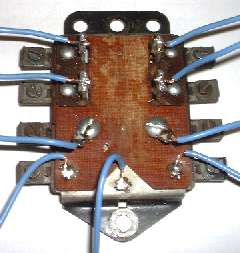
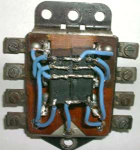
Refer to the diagram at left. Cut each wire to suitable length leaving 1/4" bare for single terminal connections and more length bare for multiple terminal connections. Twist the stranded wire snug, skewer it onto the small pins and solder it in place. For terminal 5 it is only necessary to connect the wire to one NC pin on each relay, but it is convenient to connect to all four NC pins, which will also share the electrical load for brake lights over the dual contacts. Okay, that's it. Test the new relay, put the cover back on, install it in your MGA, and it should be good for another 40 years (maybe). 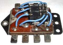  There are a few additional notes about these relays, such as the operating spec's. Expected life, Electrical: 100,000 cycles (at rated voltage and current) Expected life, Mechanical: 10,000,000 cycles (with no load) Absolute limits for ambient operating temperature: -22 to 131 dF (-30 to +55 dC) Coil voltage: nominal 12VDC, maximum 15.6VDC Coil current: 60mA (nominal) Coil resistance: 200 ohms +/- 10% Pickup voltage: 9.6 VDC Dropout voltage: 0.6 VDC The one point that stands out here is the operating temperature range. I don't suppose many people will be driving their MGA when temperature is lower than -22dF. But this relay lives in the engine compartment where I am SURE that air temperature can and does go higher than 131dF. I haven't had a problem with this yet, but if it ever fails I would post a note here. The appropriate cure for that would be to use relays with higher temperature rating, which are likely to cost considerably more. If anyone else has experience with this application I would like to hear about it. Addendum September 12, 2006 After 14 months and 10,000 miles I am happy to report that these relays are doing just fine in real world service. I have been seriously autocrossing, then parked with temperature gauge pegged and the Dutch oven going around the exhaust manifold under the carbs. I have driven a number of rough roads. I have driven the car in 100dF weather towing the little trailer at speed, and have been stop and go in heavy traffic with the temperature gauge near the high end peg, sweltering heat, scorching seats, sheet metal hot enough to burn you hand, and the carburetors suffering serious vapor lock symptoms. Through all that the new relays are soldering on, so I now have lots of confidence in this modification. I will definitely post here if anything happens to the contrary. Addendum July 12, 2009 Now 4-1/2 years and 30,000 miles in service, and it's still working fine. Addendum January, 2010 It has been brought to my attention that Moss Motors is now supplying an "upgraded" turn signal relay. If you would rather spend money than fiddle, this one uses the same sealed relays and has a circuit board rather than hand wiring. Kudos to Moss Motors for making it a commercially available item. 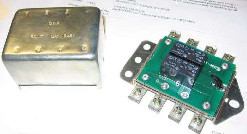 Addendum July, 2010 However, there may be a problem. Remember the 131dF maximum operating temperature rating? See next page. Addendum October 13, 2015 Today I have one reported failure of the Moss turn signal relay unit. James Keith in Greensboro, North Carolia, USA reports a connection failure between terminal #5 (brake light input and terminals #3 & #7 (brake light outputs). The turn signals work okay, so the switched output contacts (turn signal outputs) are good. This may be a cold solder joint between terminal #5 and the relay input pin on the circuit board. Not yet determined. |
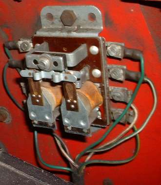
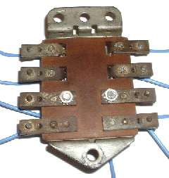
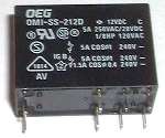 If you think it's repairable, maybe you should try fixing it. But if you're convinced that it is truly shot and beyond salvage, then you might spend an hour to replace the internal works with a pair of $5 double pole double throw 5 amp relays from Radio Shack. This little project was completed in December 2004.