The MGA With An Attitude
Twin Cam ENGINE ASSEMBLY NOTES - TC-303
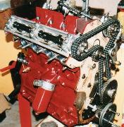
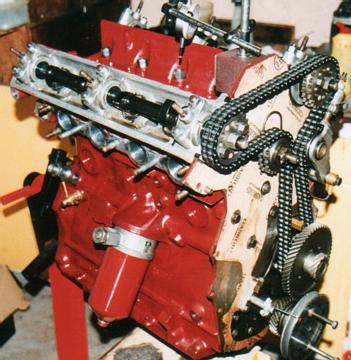
MGA Twin Cam Engine Assembly
(written by Mick Anderson)
The following article is a collection of notes of things to be observed in the assembling of MGA Twin Cam engines. To be read in conjunction with the Workshop Manual.
It does not include procedures common to all types of engine assembly.
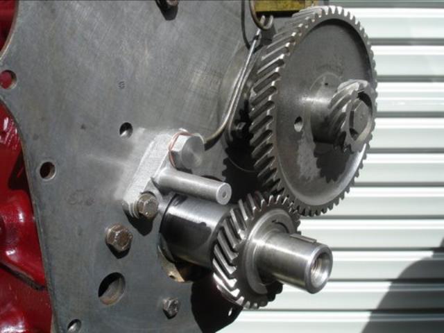
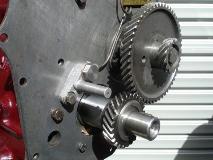
If the engine is completely stripped check the number of teeth on the oil pump drive spindle and the matching gear on the half speed shaft. If the oil pump spindle has 10 teeth the shaft must have 9 teeth. If the oil pump spindle has 11 teeth the shaft must have 10 teeth. If these two components are already fitted the half speed shaft should be turned slowly by hand for one complete revolution. The shaft should turn freely and not lock up. Also check that the timing gears themselves do not bind, as these are in matched sets. The timing gears should mesh freely and have a maximum backlash of 0.002" to 0.003".
Failure to carry out these checks can lead to the oil spindle gear and half speed shaft gear and/or the timing gears being damaged.
Pushrod oil pump drive spindles cannot be fitted as the Twin Cam half speed shaft gear is cut with the opposite tooth angle. For the same reason tachometer drive spindles from pushrod MGA's cannot be used, even if the half speed shaft was fitted with a pushrod gear, as the drive cable would turn in reverse.
Service Memorandum MG240 refers.
Before fitting the half speed shaft the free turning and the end float of the oil pump drive spindle should be checked. Place the thrust washer above the gear on the spindle, fit the spindle and oil pump, with the gasket. Tighten the oil pump to the final tension. Measure the end float of the spindle. Remove the oil pump and spindle. The thrust washer should be fitted above the gear on the spindle when finally assembled. The thrust washer should be hardened and ground steel. The approximate washer dimensions are I.D. 0.496" the O.D. 0.748 and thickness as required, approximately 0.090". There should be an end float of 0.010" - 0.020". When assembling, the top of the spindle shaft and the gear should be oiled.
The half speed shaft must have an end float of 0.003" to 0.006". Incorrect end float will cause erratic ignition timing. When fitting the timing gears the marks should be aligned as shown in Work Shop Manual Fig. A.9 even though this has no effect on setting the valve and ignition timing later. Workshop Manual General Data and Service Memorandum MG288 Sheet 4 refer.
Do not line bore the crankshaft main bearing saddles in the engine block unless really necessary. If the block is line bored the timing gears will probably bind. This will require setting up an arrangement on the bench where the gears can be lapped in with grinding paste until running clearance is correct when fitted to the engine. If line bored, extra care is required with the front and rear crankshaft oil seals to prevent leaking.
If using the original type Hepolite pistons with the solid skirt, the clearance in the bore must be more than that used with split skirt pistons. A clearance of 0.006 is
recommended. This clearance is measured at the top of the skirt at right angles to the gudgeon (wrist) pin. With modern pistons having a split skirt, the manufacturers recommended clearance may be used, but use the upper range of the clearance given.
Care must be taken when fitting the rope oil seal at the end of the crankshaft to prevent oil leakage and to avoid breaking off the narrow locating lip in the engine block. Use only graphite impregnated seals. Fit the seal in the bearing cap first, while the crankshaft is out of the engine. Press a length of seal into the groove in the bearing cap, leaving approximately 0.010 protruding from the groove. Fit a half bearing shell into the cap and press the cap against the crankshaft journal until the bearing touches the journal. Trim off excess seal at each end. Now fit a length of seal into the engine block groove in the same way, fitting a half shell bearing in the block and lowering the crankshaft into position, pressing down until the journal touched the bearing as before. Trim off excess seal. Care must be taken that no seal material is between the mating surfaces of the cap and block when later tightening the bearing cap.
The crankshaft thrust washers must be fitted with their oil grooves facing away from the centre main bearing saddle in the engine block. This is stated incorrectly in early Workshop Manuals. Incorrect fitting will seriously damage the crankshaft.
Service Memorandum MG416 refers.
The engine can be fitted in the car before the oil pump and sump are fitted, to give greater clearance. Some people prefer to fit the sump bolts when lowering the engine and the sump flange is just above the front crossmember, however it can be done with the engine fully in if the necessary five access holes are in the front crossmember.
 Before fitting the alloy timing chain cover ensure that it has a 100% contact with the steel front engine plate. Engineer's dye is best for this purpose. The steel front engine plates are often bent and the alloy cover may also have gouges. Ensure that the three dowels, as shown in the Service Parts List, two short and one long are fitted. Two dowels are fitted in the block to locate the front plate. Viewed from the front there is a short one at the top right of the block and a long one at the bottom right of the block (the bottom one also locates the timing chain cover). There is one short dowel in the top left of the front plate to locate the timing chain cover. These dowels are important to reduce wear of the distributor drive gears.
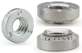 The front plate is fitted with two clinch nuts which are captive nuts pressed into position. These nuts do not have hexagon flats on them. They are required to enable two timing cover bolts to be removed and replaced where there is insufficient clearance to allow the fitting of the normal washers and nuts between the cylinder head and the plate. The holes in the front plate for the clinch nuts are larger than the holes for the other timing cover bolts. One hole is directly below the chain idler sprocket and one is to the left of that one, viewed from the front. The plain washers and lockwashers must be fitted under the two bolt heads as they cannot be fitted at the end of the bolts with the clinch nuts.
 Fitting the cylinder head.
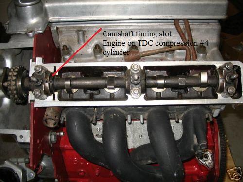
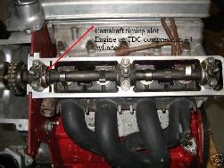
The head may be fitted without the camshafts to allow the crankshaft to be turned for other work to be carried out. If the camshafts are fitted the crankshaft must first be at TDC as per the crankshaft pulley marking and the timing slots on the camshafts must be lined up with the slots in the front bearing caps before fitting the head. Neither the camshafts nor the crankshaft may now be turned at all until the timing chain is fitted and the valve timing completed. Failure to observe this will result in the valves being bent. Check that the inlet and exhaust camshafts are not mixed (see comments below).
When fitting (or removing) a camshaft ensure that the six bearing cap nuts are tightened (or loosened) in a continuing sequence a couple of flats at a time. If this is not done the valve spring pressure will break the camshaft. When removing start from the rear bearing. When replacing start from the front bearing. Service Memoranda MG251 and MG288 sheet 4 refer. Note that the inlet and exhaust camshafts are different, in the position of the timing slot. Looking at the camshafts from the front, with the timing slot at 12 oclock, the inlet camshaft will have the first lobe at approximately 7 oclock. The exhaust camshaft will have the first lobe at approximately 5 oclock.
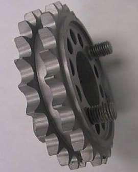
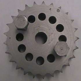
The timing chain should now be fitted. If it is an endless chain the gear on the front of the half speed shaft has to be removed. When the timing chain and the fixed and pivoted sprockets are in place the valve timing can carried out, before the alloy timing chain cover is finally fitted. If this is done the timing chain cover and crankshaft pulley will have earlier been temporarily fitted to measure the TDC position. It can be much easier to fit a degree disc and pointer to the crankshaft and use a dial gauge to find TDC for cylinders 1 and 4 and then do all the chain fitting and camshaft timing and tension with the timing chain cover off. Alternatively, the timing chain cover and the pulley can be finally fitted, with the chain and camshaft sprockets attached to the support plates on the timing chain cover. If this is to be done the chain adjuster should not yet be fitted, but the pivoted sprocket is fitted. The nuts of the triangular sprocket support plates must be slackened off slightly before the sprocket support spindles are engaged.
Ensure that the threads on the chain tensioner screw and matching alloy housing are in good condition. Service Memorandum MG288 sheet 4 refers.
Before the distributor drive shaft and camshafts are fitted there is no difference between Number 1 TDC and Number 4 TDC. When the head is fitted there is a relationship between the camshaft timing slots and the distributor drive slot.
When fitting (or removing) a camshaft ensure that the six bearing cap nuts are tightened (or loosened) in a continuing sequence a couple of flats at a time. If this is not done the valve spring pressure will break the camshaft. When removing start from the rear bearing. When replacing start from the front bearing. Service Memoranda MG251 and MG288 sheet 4 refer. Note that the inlet and exhaust camshafts are different, in the position of the timing slot. Looking at the camshafts from the front, with the timing slot at 12 oclock, the inlet camshaft will have the first lobe at approximately 7 oclock. The exhaust camshaft will have the first lobe at approximately 5 oclock.
Set the valve clearances at 0.014" to 0.015". Early documentation may show greater settings. When the crankshaft turns clockwise the camshafts turn counter clockwise. Workshop Manual General Data and Service Memoranda MG276 and MG288 sheet 4 refer.
When timing the camshafts on an engine with front timing chain cover fitted it is not necessary to remove the timing chain cover to check the alignment of the marks on the timing gears as stated in the Workshop Manual and Fig. A.9. It is necessary to remove only the chain adjuster. Leave the pivoted sprocket in position, resting on the chain. Be very careful not to drop the plunger or its internal spring into the timing chain cover opening. A full range of timing settings is available at the camshaft sprockets and the Distributor drive shaft, irrespective of the timing gear alignment.
For valve timing pull the chain tight, and attach the sprockets, trying different teeth to find the best fit for the bolts. Valve timing increments of 1.2 camshaft degrees or 2.4 crankshaft degrees can be obtained (forward one hole and back two teeth). Do not drop the sprocket bolts into the timing chain cover opening. Lockwire the bolts for the sprockets, together with the sprocket support spindle and also tighten the nuts for the triangular sprocket support plates and lockwire them. Do not forget to remove the camshaft locking tools, if used, before attempting to turn the engine. Fit the chain tensioner, being very careful not to drop the plunger or its internal spring into the timing chain cover opening. Adjust the chain tension as per the Workshop Manual Fig. A.10. Do not over tighten the chain nor the locknut.
Camshaft timing using the camshaft timing slots is normally sufficient for road use, but experienced mechanics can check the timing as per the dial gauge procedure in the Workshop Manual.
It is preferred that the valve seats be lapped with grinding paste rather than using a seat cutter. If the seats must be cut only the minimum amount of metal should be removed. Attempting to replace the valves seats should be avoided as the seats are cast in position with tapered sides, the larger diameter being furthest into the head casting.
If a vacuum advance type distributor is fitted, the vacuum tube should be removed from the distributor and left open to the atmosphere. The vacuum tube should be removed from the manifold and the hole blanked off. Service Memorandum MG288 Sheet 2 refers.
With the slots in the camshafts aligned with the slots in the front bearing caps and the crankshaft at TDC the ignition distributor drive gear should be fitted. Insert the gear with the slot horizontal and the large offset uppermost, as it engages it will turn to the 2 oclock position.
The distributor retaining bolts must be fitted strictly in accordance with the Workshop Manual. If not carried out in the correct sequence excessive wear of the distributor drive gears will occur. This is shown much more clearly in Service Memorandum MG248. Check that the distributor rotor is pointing to the #4 high tension post in the cap. If it does not the drive dog on the distributor may be 180 degrees out of position and will need to be reversed. The firing order for the spark plug leads is 1,3,4,2 viewed at the top of the cap in a counter clockwise direction (fit #4 first as described above).
Notes:
| |
With the camshafts slots aligned with the bearing cap slots the engine is on number 4 cylinder compression. Both the camshafts and the ignition are set on number 4 cylinder.
Note that the inlet and exhaust camshafts are different only in the position of the timing slot.
Remember that when the crankshaft is turned clockwise the camshafts turn counter clockwise.
If removing the inlet manifold ensure that the nuts hidden inside the carburetor throats are removed, as shown in Workshop Manual Fig. A.1.
Cylinder head nuts should not be undone while the cylinder head is hot.
Copper head gasket surfaces should not used against the alloy cylinder head surface.
It is strongly recommended that the SU carburetors be soft mounted as per Stage 3A or 4A of the MG factory Special Tuning booklet for the pushrod MGA.
Static ignition timing is TDC for 9.9 CR pistons and 8 degrees BTDC for 8.3 CR pistons.
|
For a list of Confidential Service Memoranda for the Twin Cam see article TC-120
|