For the MGA front shock absorber (top of page), bump travel (upward) moves the top piston toward the valve and the bottom piston away from the valve. Port B therefore will be the supply port for the bump direction, while Port A will be the supply port for the rebound direction.
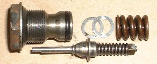
In bump action high pressure at port B will push the small center poppet off the valve seat, pulling on the central rod to compress the smaller inner spring. Hydraulic damping action in this direction is a function of force on the smaller spring, and is adjustable (within a small range for fine tuning) by way of the adjusting nut B.
In rebound action high pressure at port A will push the larger concentric poppet off the valve seat, compressing the larger spring A. Hydraulic damping action in this direction is a function of force on the larger spring, and is adjustable (within a small range for fine tuning) by way of adjusting shims A.
For very fast motion (big harsh bumps at speed) the small bore of the port orifices will further restrict flow to create higher pressure at higher flow rates. Therefore fast motion for big bumps will give more resistance and stronger damping, while slow speed up/down oscillating motion will give lower damping and reasonably soft ride.
Before you try adjusting these things, bear in mind that the small nut and shims were intended for fine tuning the intended pressure limits, and adjustments in this manner will make only small changes in damping force. For pressure change on the order of say 30%, you would have to install different springs. There are other tech articles here showing modifications using a pair of external flow control check valves to make these units finger adjustable.
If you compare MGA shocks to MGB shocks, you may notice the MGB shock bodies are opposite end around compared to the arms. This makes the shaft rotate opposite directions, and therefore oil flows in opposite directions for bump and rebound. The functions of ports A and B will then be interchanged. It is common for blow-off pressure to be 2 to 3 times higher for rebound than for bump. So for MGA the port A will have much higher blow-off pressure, while for MGB the port B will have higher pressure. Even if these two applications call for the same damping rates, the control valve assemblies will have different springs to provide the differences in required pressures. For an example of shock absorber damping specifications you may refer to the "MGA Twin Cam Engineering Technical Data" book, looking into Section M: Suspension Dampers (197-KB pdf document).
|