The MGA With An Attitude
Front Shock Absorber ASSEMBLY CONFIGURATION - FS-118
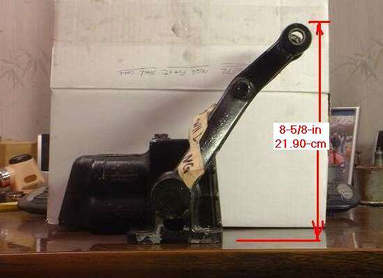
Someone received some MGA front shock absorbers that had been disassembled, so the question was how to position the pistons relative to the arm when reassembling it. In schematic it looks approximately like the diagram above, but in fact the arm may be slightly higher when the pistons are at mid stroke. To get it right I have placed an MGA front shock absorber on a table to measure full travel of the arm.
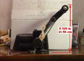
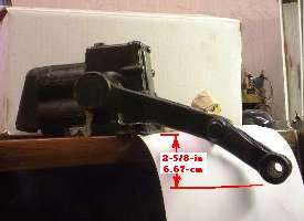
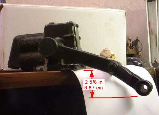
With the arm raised to maximum height, the top of the arm end eye is 8-5/8-inches (21.90-cm) above the mounting surface. With the arm lowered to minimum height, the bottom of the arm end eye is 2-5/8-inches (6.67-cm) below the mounting surface. Click for larger pictures.
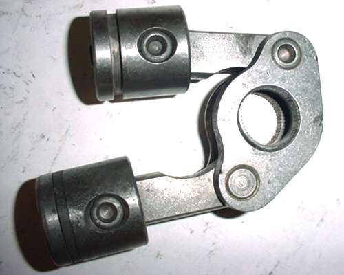
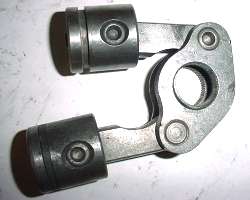 The input arm drives a rotating shaft that drives a bell crank (rocker arm) that in turn drives two pistons in opposite directions. It is common for this vintage shock absorber to have a piston ring on one piston only. The metal piston seal is on the upper piston, while the rubber seal (if there is one) goes on the lower piston (which is the rebound piston for MGA). For MGB the housing is opposite end around with the piston end in same direction as the input arm. For that application the lower piston is the bump direction piston. I will guess the reason for only one piston seal is to allow a little leakage to let oil in and air out for purging immediately after filling with oil.
|
|