The MGA With An Attitude
ORIGINAL TYPE SWAY BAR Adapted On Top -- FS-103
This one is larger diameter than the factory issue, and has an
adaptation for aftermarket type frame mount bushings.
FS-103 is a slightly nervous course in how to install what we currently call an "original type" front sway bar. The real original MGA front sway bar was 5/8 inch diameter, and the frame mount brackets were thin metal parts which attached directly to the top of the front frame extension and used a very thin nylon bushing. What we have available today are sway bar parts which were originally intended for the MGB, but which can be retrofit to the MGA with the understanding of "some fabrication required".
The sway bar itself is very similar to the original MGA factory part, but will often be larger than the original 5/8 inch diameter. If you were crafty you might fabricate your own thin metal brackets and thin wall nylon bushings, and mount the new sway bar in similar fashion to the original design. The first problem is that as the sway bar gets larger in diameter you quickly run out of space in the original location above the front frame extension and below the body air pan. The larger rubber grommets and brackets which are off the shelf parts from the MGB kits are definitely too large to fit above the MGA frame without some serions cutting and welding of the frame to make more space, or some difficult or obnoxious reforming of the sheet metal in the MGA body air pan.
Here we have method which was developed in a home garage by Mac Askari, member of Bakersfield British Car Club (BBCC), who fabricated the brackets shown in the pictures on this page. This method accomodates the larger frame mount rubber bushings from the MGB (and commonly available as aftermarket parts), and does not require any modification of the MGA frame. It does however require use of the later model MGA frame front extension with the depression on top where the sway bar crosses over the frame. This modification was introduced by the factory in April 1959 at car number 66574, and included the last 2200 or so 1500's. It did not appear on the Twin Cam model until Jun 1959 at Twin Cam car number 2275, about a month after introduction of the 1600 body style. Most new replacement parts for the front frame extension currently available will be the later type with the top indents. If you're buying a used part, be aware of the difference and look to get the later type if you want a top mounted sway bar.
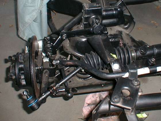
Original type sway bar fits above the front frame extention.
The trick here is to fabricate a new bracket which fits on the inside of the MGA front frame extension and carries the large MGB rubber bushing a little below the top surface of the frame. The braket is made from steel sheet and starts with a shallow bend at the bottom to match the slope of the frame. This angled bottom tab on the new bracket will attach to the frame at the location of the original (Windtone) horn mounting bracket, and when finished the horn can be reattached in the same location. From there the new bracket extends straight up to a point where it makes a right angle bend outward (toward the frame rail) to form a flat top surface for mounting of the MGB rubber bushing. As the new bracket approaches the sloping side of the frame once again, it will bend upward at the original angle to lie flat against the side of the frame near the top edge. This is the starting form of the bracket with three bends and a near vertical top flange which will be formed later to match the top surface of the frame. This top flange of the bracket also has a notch where it will straddle the sway bar without touching.
There is no welding involved here and the bracket does not extend or lay in the depression where the sway bay crosses the top of the frame extension (you need all the room you can get in that spot).
Drill two holes in the bracket to match the spacing of the holes on tbe commercial bracket which will secure the MGB rubber bushing. Then install the bushing on the sway bar and attach the bushing to the new bracket. Ditto for the mirror image new bracket on the opposite side.
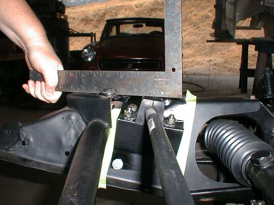
Set the sway bar on the frame with the bushings and new brackets attached. Position the bar concentrically (centered) above the notch in the top of the frame. Block up the bar about 1/8 to 3/16 inch above the frame to allow for compression and wear of the rubber bushing in operation without having the bar touch the frame. The top of the bushing hold down bracket needs to be no higher than flush with the top of the frame where the body will sit with the horizontal air pan immediately over the sway bar. With the sway bar fixtured in this position, mark and drill the two holes in the bottom flange of the new bracket to match the location of the original horn mounting holes in the frame, and install those two bolts on each side.
Once the new brackets are secured at the bottom edge as noted, you can hammer down the tabs on top to form them over the top of the frame to lie flat against the top and to follow the contour of the original frame. Then mark and drill holes in the new bracket to match the holes in the top of the frame which were for mounting of the original type sway bar brackets. You might form and attach the front tab first, as this one has a straighter bend and will be easier to form. With three bolts holding the new bracket it should be easier to hammer form the rear tab to closely match the contour of the frame, then drill the bracket and install the last attaching bolt. The end result should look like the pictures below.
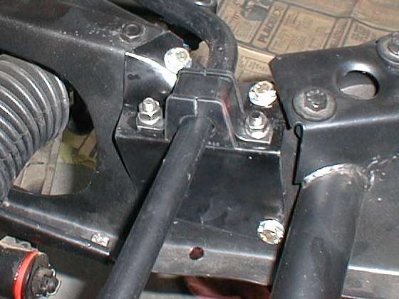
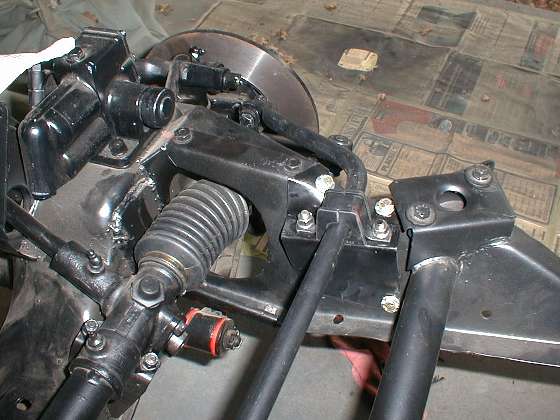
New bushings and brackets mounted below the top of the frame.
At the right is a picture of a template that can be used to fabricate these special brackets. Click on the picture to get a full scale printable image. Be sure to display it at full scale, even if it doesn't fit in your browser window. The larger image is full scale at 100 dots or pixels per inch. The overall image is 750x1000 dots, intended to be 7.50" x 10.00" in size. You might use 8-1/2" x 11" paper, set your printer margins to 1/2" all around, and print the image to fit the remaining space. Otherwise print it dot for dot at 100 dots per inch, or scale=3X at 300 dots per inch.
Make these brackets from 14 gauge (.080") steel sheet, similar to the thickness of the front frame extension. Do not try to skimp and make them from 16 gauge material (.060"), as it would definitely not be strong enough to bear the harsh loads required.
The rest of the installation is bolt in using the standard parts for the end links, and the spring pans and front a-arm brackets which were intended for use with the original type sway bar links. One more picture of the finished installation below.
Note that when fitting the original type front sway bar to the MGA which is already assembled, the factory workshop manual gives details for assembly sequence. It calls for removal of the front bumper, the front valance panel, the horn(s), and the front frame extension. After installation of the sway bar on the front frame extension, reassembly is the reverse of disassembly, and the end links are installed last.
New bushings and brackets mounted below the top of the frame.
The only welding done on the initial brackets was for the bolt coming up from underneath of the platform. Once you install the bracket, you can not get your hand or a wrench to put the bolt through from the bottom of the platform. Mac's solution was to weld the bolt head under the bracket and turn the nut on top to install the rubber bushing bracket. I would prefer to add a flat steel strap under the bracket and weld the bolt heads to that, so the cheap and easy flat strap and bolts are replaceable later if the bolts should get damaged. The steel strap would also serve as a reinforcement plate to spread the stresses of the atachment bolts out over a larger area on the bracket to reduce the likelihood of getting stress cracks in the new bracket with harsh use of the new sway bar.
For a differnt size sway bar, or maybe a different model of rubber bushing, the platform (that is where your rubber bush and the metal bracket sits) can be located anywhere (up or down as needed). You need to consider the depression where the sway bar crosses on top of the extension. If you go too low then the bar will either be rubbing on the metal in the depression or not be able to cross at all. Have the two tabs come straight up a little first and then fold or bend over on top of the frame after the bar is positioned where you want it.
|