The MGA With An Attitude
Body Sill Replacement - RT-621
Sill Plate Replacement
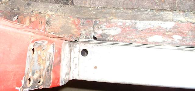
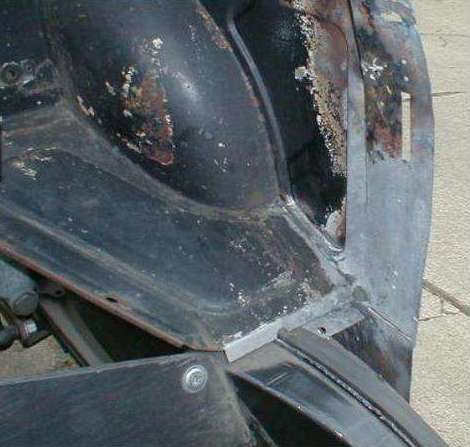
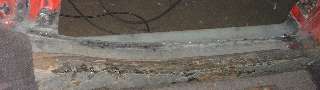
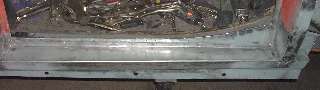
Now that the body sill and pillars are back together it's time to tend to the slightly rusty sill plate that I have been so diligently saving for the spatial reference. The picture below right shows some rust perforation. There was also a LARGE number of holes in the vertical flange left from drilling out rocker panel spot welds 30 years ago, so I decided to replace most of this panel.
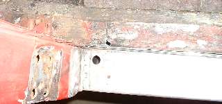
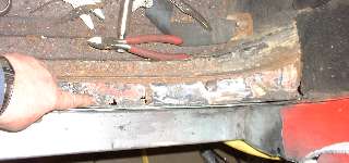
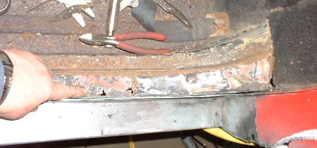
Photo above left shows a cut in the sill plate just aft of the A-post. This was done partly by lifting the panel and cutting the first inch with the abrasive cut-off grinder. Then the small body saw was used to cut the rest of the way between the frame and body sill. The short piece of sill plate from there forward to the body mount bracket was in good condition and was still welded to the inner body, so I kept that piece. The back end of the sill plate was disassociated from the body sill when the sill was being cut out for replacement. The tail end of the sill plate was (once) spot welded to a small tab under the battery shelf, but that joint pulled apart easily once the rest of the strip was free to move. I will take care of reconnecting that joint later when the body is off the frame.
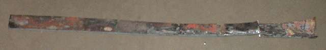
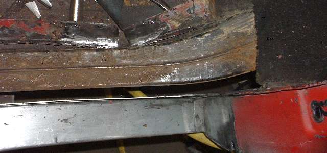
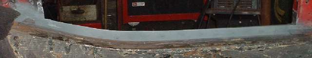
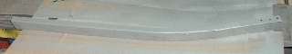
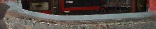
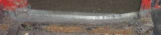
This picture shows the old sill plate after removal. This piece would serve as a template for making the new plate. Photos below show top of the frame after the sill plate was removed.


The frame had some surface rust on top along the back half of the door opening, which is another reason to be happy about doing this job now rather than waiting until the rust might get worse.
ADDENDUM February 10, 2012: -- How do you make this joint?
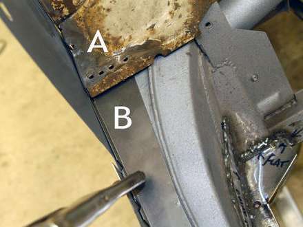
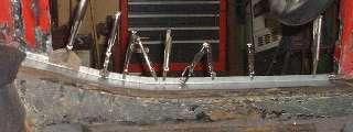
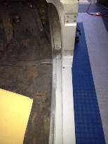
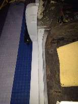
In the photo below left, "A" is the forward edge of the boot floor along side of the battery cover (right side of car). "B" is to be the new sill plate that lies on top of the outboard half of the outer frame rail. Note that "A" is a little out of position, as the bottom notch should straddle the welded ridge on the frame. "B" should get wider at the back following the weld ridge on the frame. The four holes in "A" were drilled to remove spot welds when removing the old sill plate.

The center photo above shows a joining piece with a "Z" shape the is tucked up under the boot floor (left side of car). This is spot welded at the top surface (where you see holes in the prior picture). The sill strip then sits on top of the joining piece and tucks under front edge of the boot floor. Photo at right above shows the assembly with two rows of spot welds.
Photos above supplied by: Landon Hunter, central PA, USA,
Chuck Schaefer, West Chicago, IL, USA, and Randy Brown, Highlands Ranch, CO, USA.
When the body is bolted on the frame, all of the bolted joints have 1/8 inch thick cork packing. When installing the body sill strip you can put a layer of corrugated cardboard under the strip to retain a space for soft foam rubber packing to be installed later (assuming the body will subsequently be lifted off for underbody and frame painting). If you will not be removing the body later, then you need to install the real packing under the sill plate before it is welded in place. 1/4-inch close cell foam rubber makes good packing for this joint (although it was probably felt material originally).
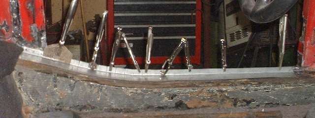
Making the sill plate was fairly easy using the old one as a template and adding a 5/8-inch flange. This piece has a straight edge along the sill, so it can be bent to a right angle by clamping and hammering over the edge of the work bench. There is a section about 9-inches long where the pate curves upward (then continues straight again). I don't have a flange shrinker/stretcher tool, and I don't want to buy one for this limited use. To avoid a lot of hammer forming I take the easy way out and cut slits in the flange an inch apart to allow it to bend easily the "hard way". Then I press the sill plate into place to form the shape I want, leaving a small space underneath to allow for the body to frame packing. Once I have it clamped into place I tack weld the slits to make the piece ridged again.
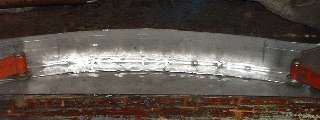
With the sill plate in final shape I can take it to the work bench and clamp it down to keep the flange flat while I weld the slits shut. There you see the welds, and then you don't see them after the magic grinding.
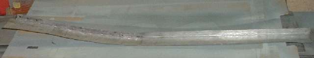
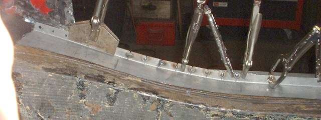
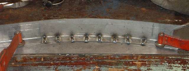
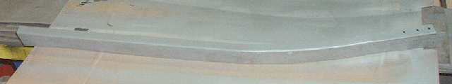
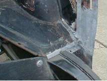
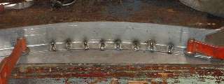
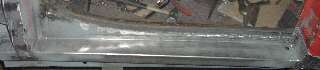
Photo above is the finished sill plate with flange and curve and three holes punched at the tail end for plug welding to the inside of the body aft off the door. Below left is the flip side of the sill plate with the flange sprayed in zinc primer. Below right is the inboard side of the sill above the frame also sprayed with the zinc primer.
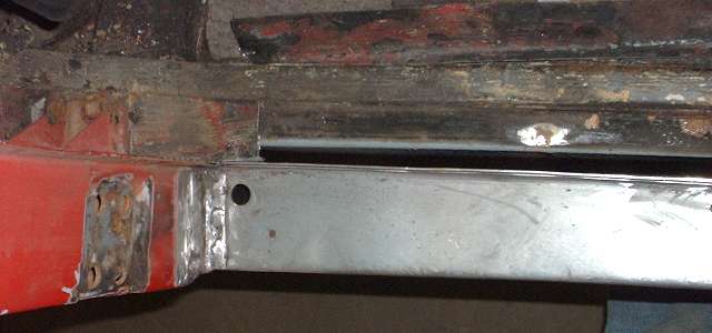
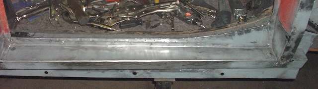
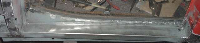
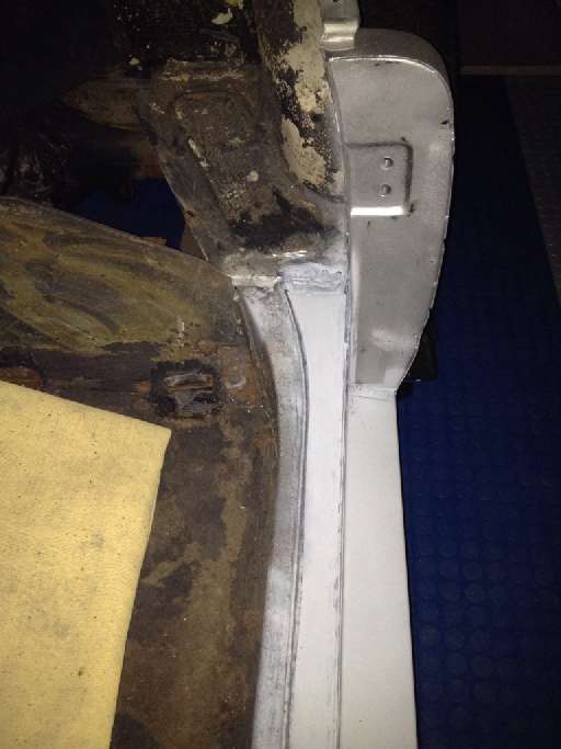
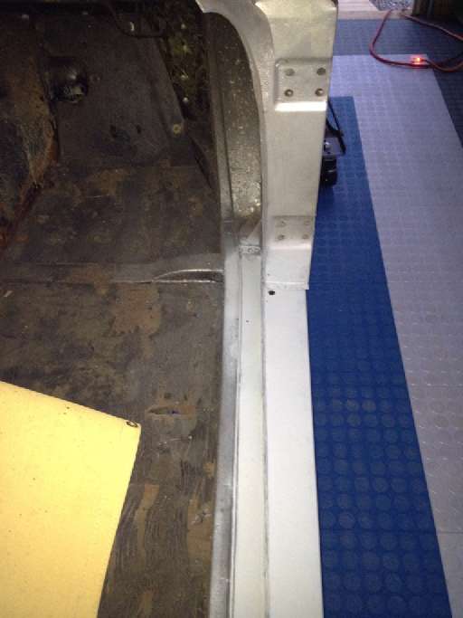
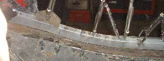
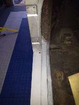
Photos immediately below show inboard and outboard views of the left side sill plate after installation. Plug welds aft of the door opening are ground flush. A butt weld just aft of the A-post is ground flush. The vertical flange along the door opening is spot welded. Once the sill plate was installed I ran the angle grinder along the top edge to produce a uniform flange height and even edges all along, and followed that with deburring. The rocker panels will not be installed until after the body is removed from the frame. (8 Mar 08)
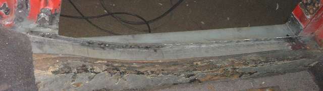
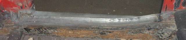
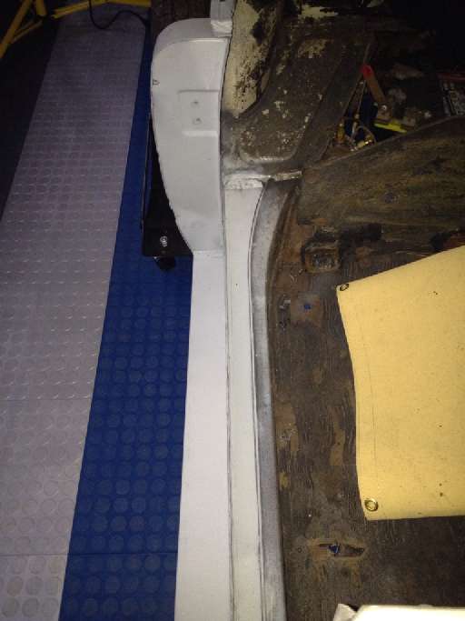
Skip ahead one day, and there (below) is the new right side sill plate installed. Pretty much the same except I saved a short piece near the back on this one and ran the new piece all the way forward to the body mounting bracket. (9 Mar 08)
Addendum January 2012:
Some additional pictures of new sill plate installation from Jeff Allen in Massachusetts, USA

|