

 The MGA With An Attitude
Body Sill Replacement - RT-614B
A Simpler Point of View, Box Panel Forming

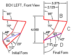
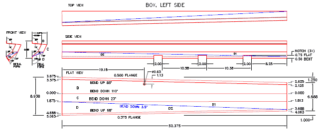
 Now four years later we have a simpler point of view for forming this part. Well, at least a different point of view that might make it easier to understand. That troublesome surface "D" with progressive bends and a twist can be defined much simpler with a slight change of geometry to turn the progressive bends into simple bends and the twisted surface into two triangles. Starting with the prior drawing, divide surface "D" into two triangles D1 and D2 by drawing a new line from corner to corner as shown by the blue line in these drawings. (Click for larger images).

When bending up the part put a 3-1/2 degree bend on the new line. The flat blank before bending is the same, and the end view after final forming looks the same. Difference is the lower surface "D" is now slightly convex on the outboard side of the box, the previously twisted surface is now two flat triangles, and those pesky progressive bends are now magically simple bends.
Notice change of the "initial" bend angle in the end views. You don't have to bend these in any particular sequence. I only show the triangulation bend done last as it seems easy to view that way (and didn't require so much adjustment of the drawing). I'm not sure how modern bending equipment might handle three surfaces converging at a common intersection with an acute point. As I said, simple in theory, and easy enough to draw, but how you actually do it with available tooling is a good question.
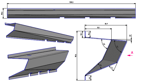
Below we have a 3D drawing of the part with simple bends. There is a fellow in Germany who is about to punch one out on an automatic bending machine. This should be interesting. I wonder who gets to test the prototype? See next page for progress photos.

|