The MGA With An Attitude
Body Sill Replacement - RT-614
Box Panel Forming
 You might remember the small drawing of the sill box panel from about 10 pages back. It finally evolved into the finished drawing shown at right and below. After waiting a few weeks for a friend of a friend to get another friend to bend up the panels on a press brake, I got tired of waiting (keeping one eye on the calendar). Having neither a press brake nor a bending brake with a five foot span, I decided to try malletizing the part. It starts as usual by physical layout and scribing lines on the sheet metal, followed by cutting it out with the electric sheer, hammering the edges flat and deburring.

See next page for additional details on the single 5/8-inch diameter hole.
I "borrowed" a 2 x 8 plank I had been using for decades as a garden tractor ramp, now to be used as a clamp bar. The sheet metal was positioned on the work bench, heavy plank on top, and clamped down with a pair of "pony" clamps. The first bend was down the center on the 0.000-0.000 line, forming the sheet downward over the edge of the bench to 90 degrees. This is of course MUCH more work than hammering down a half inch flange. With 4 to 5 inches of metal hanging out, a hammer blow near the bend line can put a sizeable dent in the sheet without bending it much. After some head scratching I did the expedient thing, put on leather gloves, put two hands flat on the sheet extension and sort of jumped on it repeatedly. This bent the sheet down roughly in a narrow parabolic curve. Once it was down about 75 degrees I had at it with a hammer. The body hammer wasn't heavy enough to do much but make noise. The ball peen hammer was putting irritating dents in the metal. I finally settled on a two pound steel hammer with a wide and slightly crowned face. The trick here is to press down fairly hard on the edge of the sheet, and then whack it near the bend line. As work progressed I was throwing down a couple tons of iron and taking breaks to avoid muscle cramps.
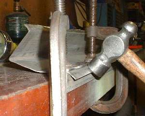
As the metal was approaching 90 degrees near the side face of the bench I added another tool. I found an old hammer head (no handle) from a two pound cross peen hammer, slightly crowned on one end. I ground the face flat and rounded the corners slightly, then used it as a flattening punch while hitting it with the "two pounder". Thanks to my laminated rock maple work bench the bend finally came to 90 degrees with an acceptably sharp corner. I even managed to hammer down most of the previous dents so it was looking better.
Then I needed another 20 degrees to bring that 90 degree bend up to 110 degrees, so out came the circular saw with an edge guide. Taking an educated guess that there would be about 2 degrees spring back in the sheet after bending, I cut the angle on the plank at 22 degrees. In the end that turned out to be a very good guess. The sheet metal was turned over with the leg up, clamped down once again with the plank, this time with the beveled edge of the board forward. To be sure the plank wasn't going to move while I was pounding on it, I screwed a couple bits of one inch board to the bench behind it for a back stop. Then came more hammering. About this time it dawned on me that my plastic face two pound dead blow hammer might also do a good job with a little less noise and maybe less denting of the metal. This was also a good choice. Technique here was similar, press firmly on the edge of the sheet and whack it near the bend line. I must have been getting better with the swing, and it was only another 20 degrees, so in due time the trusty dead blow had the first bend back another 20 degrees and verified with an adjustable triangle.
 The second bend was to be made slightly higher than the top edge of the plank, and not quite parallel to the first bend. I soon found some 3/16 inch plywood (left over from a shipping a gearbox) and some 22 gauge (0.030") sheet metal (previously used to patch the daughter's old stock car). Beyond each end of the work piece went a piece of 18 gauge so start flush with the work piece. Then place one layer of 3/16 plywood. Add to this some sheet metal shims, .030" at one end, .048" in the center, and .078" (.048+.030) at the other end, then place the plank on top of the shims and clamp it all in place. This brought the plank up to the right height with an appropriate 1/16 inch slope along the length of the work piece, putting the top of the beveled edge in the right place for the second bend.
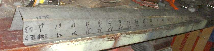
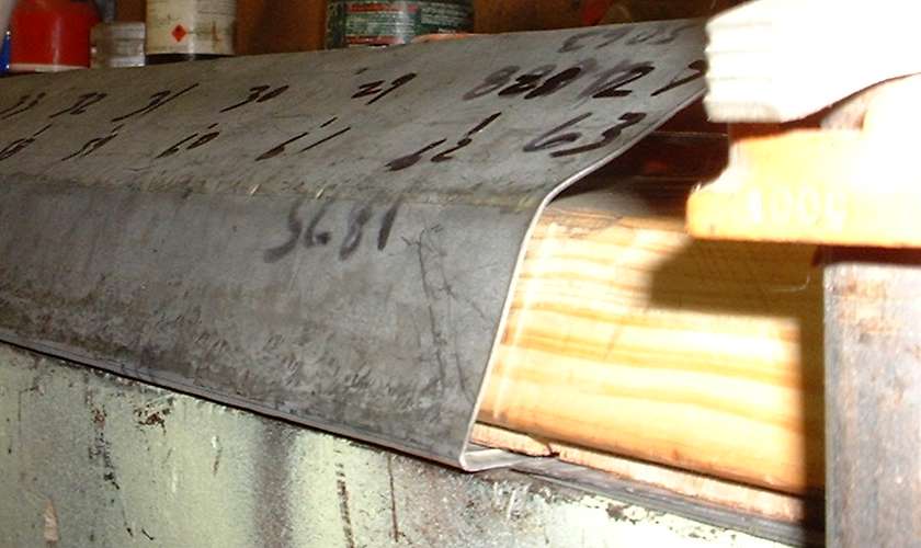
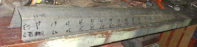
 Getting back into the rhythm again, press here, hammer there, work back and forth along the length of the part checking periodically with the adjustable triangle, and in due time I had the second bend over to a base angle of 23 degrees. Then comes the real fun, considering that "surface D" has a 20 degree twist over the length of the part. Using a tape measure and a felt tip marker I made tick marks at 2-5/8 inch intervals long the part, then marked the intended bend angles in one degree increments. With more malletizing, and checking with the adjustable triangle periodically, I soon had the second bend into a progressive angle going from 23 degrees at one end of the part to 43 degrees at the other end. That was followed by more hammering on the initial 20 degree face to make that flat again, and give a crisp corner to the second bend.
|
I thought it might be a good idea to make the flange along the bottom twisted edge next, keeping the simpler top edge flat until the trickier deed was done. This bend requires clamping and working on a short section, perhaps 6 to 8 inches at a time, because of the progressive bend angle prevents clamping the full length of the part at once. So clamp it down, hammer a little bend, move clamps, hammer some more, and repeat the process numerous times until the flange is formed progressively from 48 degrees at one end to 68 degrees at the other end. Checking the angle(s) while work progresses is easier here, as the opposite edge of the part can be used as a guide for a straight edge, with the goal of forming the flanges all into a common plane.

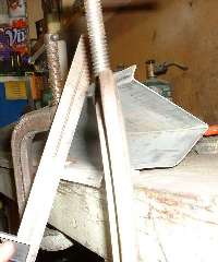
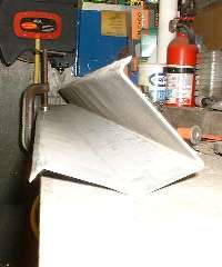
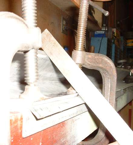
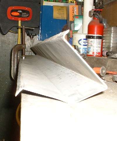
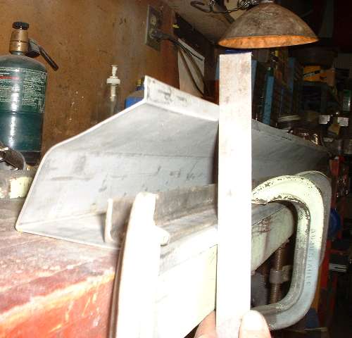
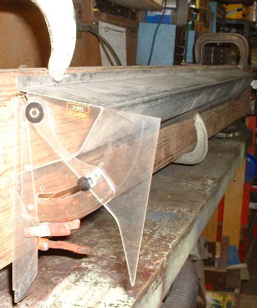
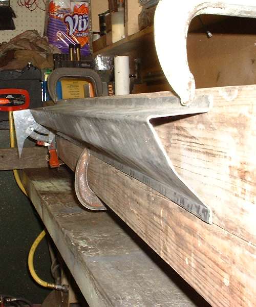
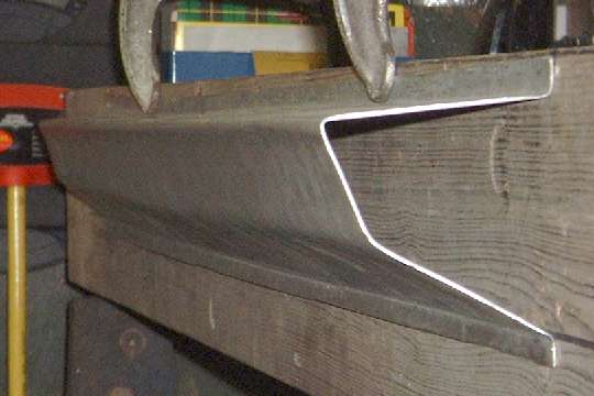
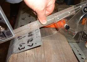
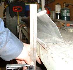
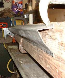
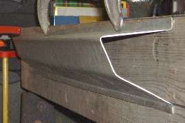
I am cheating a little with the pictures, as I had both flanges done before I picked up the camera. Before the top flange was formed I would position the top corner of the straight edge at the scribe line for the top bend while inspecting the bottom flange. Photo above left shows checking the bottom flange at the back end of the part (left side sill box). Center photo shows checking the bottom flange at the front end of the part. Photo on right above shows the finished part with the rear end clamped flat and the front end showing the 20 degree twist.

After all that, forming the top flange was easy. This required only a single setup using an angle iron for a clamping bar and hammering the flange over the edge of the bench to an 85 degree angle. I used multiple c-clamps at 12 to 15 inch intervals, moving one at time out of the way as I was working in the vicinity. Once the flanges were formed I could lay the part on a flat surface and do final flattening of the flanges with a flat faced body hammer. Final touch was to grind the edges smooth and deburr the part.
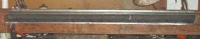
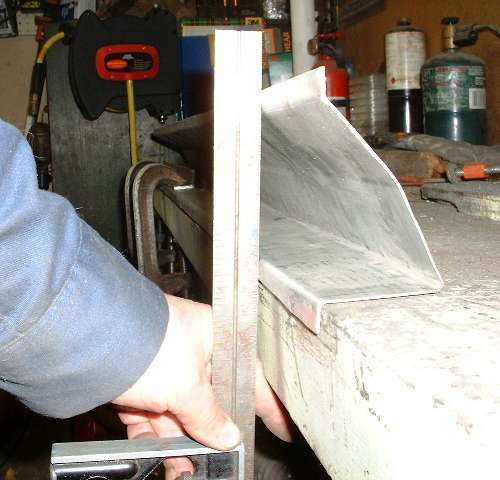
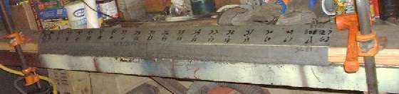
I have clamped the finished part to the plank to show the final form in proper orientation. So there it is, wide at the front, narrow at the back, a perfect 5 degree angle on the top surface, 25 degrees from vertical on the side, 20 degree twist on the bottom surface, and 4 inches across the flanges. (31 Jan 08)

 With due diligence and more cutting, bending, hammer work, trimming and deburring, there's the box panel for the other side of the car. Having done it once before, this one went a little quicker and with less hammer marks. It required about the same total energy application with the heavy hammers, meaning I got all the muscle cramps in one day. This is definitely a love of labor (or hate). If you think your time is worth as much as minimum wages you might be better off paying for preformed parts.
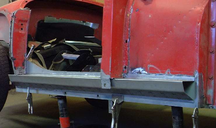
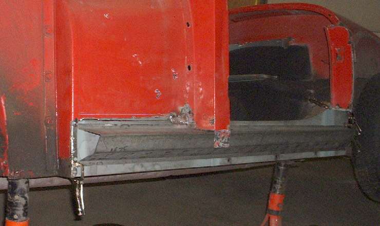
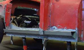
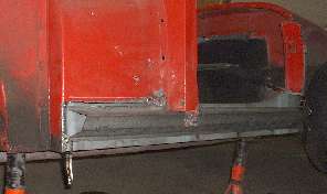
Photos below show them clipped onto the car for trial fitting before installing end plates or internal gussets. With the sharp bends done these box panels are already quite stiff, even without being welded. Once the gussets and end plates are added, and they get welded to the flat inner panels to make a closed box, this structure will have high torsional stiffness as well as the bending strength. This leads to the following hint. If you need to change the shape of this box panel, do it now, before welding anything. Once the end plates and gussets are installed it would be very difficult to re-form anything more than the edge flanges. (10 Feb 08)
|