The MGA With An Attitude
ROUTING Under Chassis, Fuel, Hydraulic, Electric - RT-120
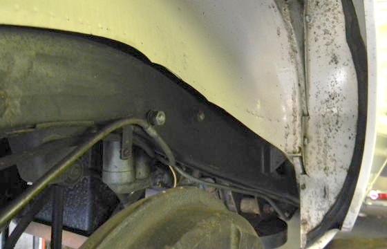
This shows proper under chassis routing and mounting for fuel pipe, brake hydraulic pipe, wiring harness, and main battery cable. Thanks to Jim Ferguson in North Carolina for the picture. Forgive the fuel line being copper when it should be steel.
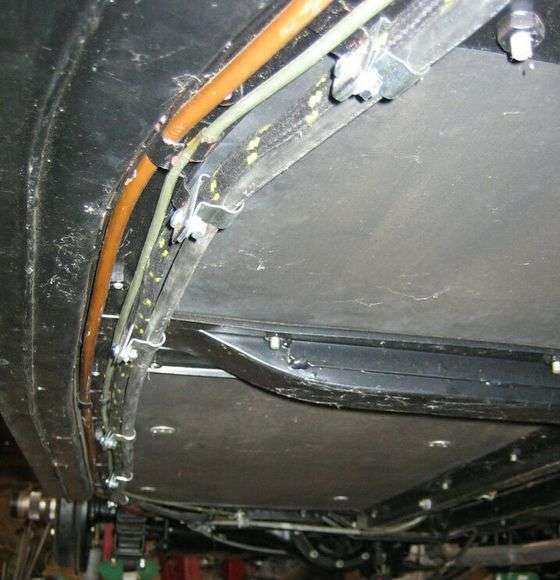
 Fuel and brake pipes run underneath the floor board mounting rail straddling the weld nuts. The larger fuel pipe is best protected in the corner next to the wide frame tube. These pipes are held in place by steel tabs that are welded to the frame and bent inward and upward around the pipes. The wiring harness and main battery cable are mounted just inboard of the floorboard mounting rails. These cables are held in place with large (double pass) "P" clips turned in the upward direction to put the cables as high in the chassis as possible for best protection. The clips are screwed to vertical tabs that are welded to the frame at the inboard edge of the floor mount rail.
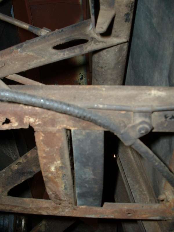
Where the fuel pipe and brake pipe come to the leaf spring, the brake pipe is routed inboard of the spring bracket on the frame so the pipe does not go under the spring bracket at a point commonly used for jacking. The battery cable is also routed inboard and upward at the same location. The wiring harness will continue rearward along the outer frame tube following the upward arch over the rear axle. At the highest point of the arch the harness is secured to the outboard side of the frame with a "P" clip screwed to the same weld tab used for attaching the cable grounding wire ring lug and the fuel pipe from tank to pump.
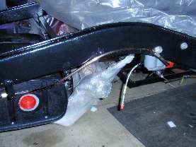
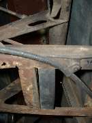
Now for one of the most often asked questions. The fuel pipe from tank to pump runs on the outboard side of the frame and turns inward under the frame just forward of the "P-clip" attachment point. From the pump forward, the pipe runs under the frame just aft of the front spring hanger, then turns straight forward under the frame again (before it gets too low) to run forward on the inboard side of the frame underneath the floor board mounting plates. The trick here is to position the pipe so that it does NOT run under the frame at any point where a hoist pad or jacking point is used to lift the car. It must run beside the spring shackle, not under it. Below is the best picture I have so far of the original installation. I really need a picture form the bottom.

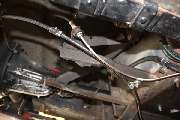
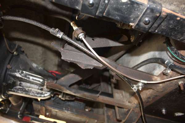
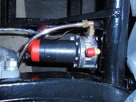
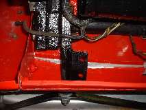
Brake pipe from side frame connects to the rear flex hose. There should be a P-clip for the pipe on the underside of the battery tray extending outboard to hold the pipe along side of the battery tray just before it bends upward to meet the hose. The bolt for the P-clip here should be a pan head screw (#10-32-UNF x 1) with the head on top under the battery. The battery tray originally includes L-shape rubber pads front and back to cushion the battery. The thickness of these pads elevates the battery enough to not contact the bolt head underneath. If the pads are left out the battery may be damaged on the bolt head. It is very common for this bolt and the P-clip to be missing (perhaps intentional).
The same screw carries a tube spacer followed by another P-clip holding the hand brake cable, then a lockwasher and hex nut. Dimensions of the spacer tube are 7/32" I'D x 3/8" O.D. x 1/4" length.
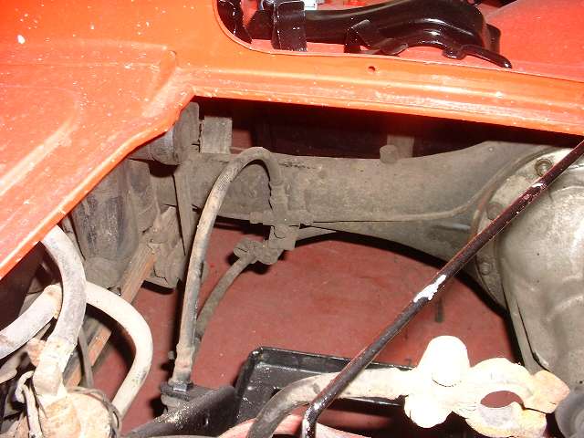
The rear flex hose is anchored in a bracket on the side of the battery carrier frame and loops upward to terminate in a three-way block bolted to a bracket on the rear axle. From the three-way block pipes run left and right along the axle housing. Pipe going to RR wheel turns upward to loop over top of housing, then down in back to get to the banjo fitting on the slave cylinder. The slave cylinder moves in a slot when brakes are applied.
 There must be no other anchor point along this short brake pipe, as it has to flex a little to accommodate motion of the slave cylinder.
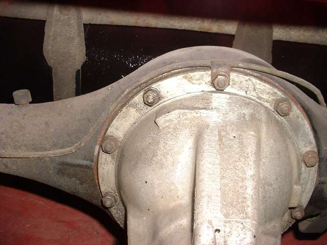
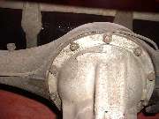
 Brake pipe heading for LR wheel loops over the top of the differential where it is secured with a P-clip at top bolt. The Service Parts List shows this clip located one bolt closer to the 3-way fitting. After the P-clip the pipe turns rearward and downward to go behind the housing as it runs outboard. Half way out along the left side of the housing there is a band clamp around the housing to secure the pipe to the housing. Again the slave cylinder moves a bit in operation, so the pipe has to flex a little to accommodate the motion. Brake pipe heading for LR wheel loops over the top of the differential where it is secured with a P-clip at top bolt. The Service Parts List shows this clip located one bolt closer to the 3-way fitting. After the P-clip the pipe turns rearward and downward to go behind the housing as it runs outboard. Half way out along the left side of the housing there is a band clamp around the housing to secure the pipe to the housing. Again the slave cylinder moves a bit in operation, so the pipe has to flex a little to accommodate the motion.
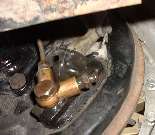
For more information on the 3-way fitting and the banjo fittings on the rear slave cylinders see HT-112 - Rear Brake Banjo and 3-Way Fittings. This shows the termination of the rear brake pipe at the banjo fitting on the slave cylinder. The "V" shape banjo fitting is the later type as fitted to my 1500 (August 1957 production). Earlier the banjo fitting was straight with ports on opposite ends, putting the bleed nipple on the bottom (pipe input in same position shown). There is also a change of threads and flare nut fittings on these banjo fittings as well as a change of threads and flare nuts on the pipes at the 3-way block. All of these fittings and blocks and pipes changed at the same time, commencing with car number 27989 for disk wheel cars and car number 28540 for wire wheel cars (March and April 1957). You must have a matched set of brake pipes and fittings for the rear axle.
 Where the side harness joins with the rear harness you normally have a bundle of snap connectors. This is directly behind the right rear wheel and subject to road splash, so it will inevitably give problems after a while. My solution some years on was to remove all bullet ends and join the wires with gas tight crimp connectors, including silicone dielectric grease inside the connector tubes. Then I wrap the entire bundle with tape to keep the grease in and water out, and further attach it structurally to the frame to prevent vibration and shake that could stress the connection joints. This method has served well for over 100,000 miles with no connection problems. Note that this harness joint does not need to be disassembled to R&R the wiring harness, as I did exactly that with the body restoration work in 2007-2008.
|