The MGA With An Attitude
THIRD BRAKE LIGHT Relay Trigger - ET-240B
The MGA 1500 model uses a common lamp for brake light and rear turn signal, like many other cars prior to 1960. This requires a relay unit to disconnect one rear lamp from the brake light circuit and connect it to the turn signal circuit for flashing a turn signal. See article ET-101F. Adding a third brake light to post 1960 cars is electrically as easy as plugging into the brake light wire at rear of the car, but earlier cars are more of a challenge, requiring a logic circuit to monitor the two separate turn signal wires and determine when the third brake lamp should be lit.

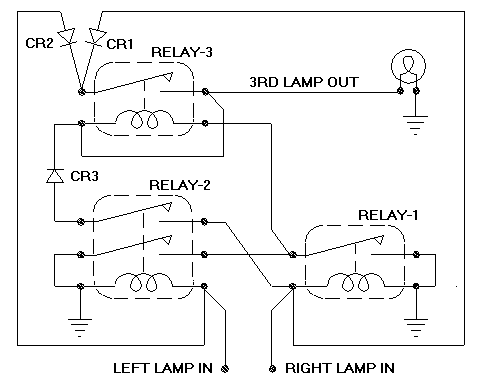
Here is a diagram showing a logic circuit for this function that can be assembled using a few miniature relays and diodes available at a local electronics shop. Using potted relays and solder connections should make it fairly environmental proof without need for additional encapsulating. Otherwise the whole assembly could be dipped or brush coated with epoxy.
With both input lamps on two relays are actuated providing two ground connections and one additional contact. Power from right lamp goes through the left relay contact to operate the third relay, switching on the third lamp. Two diodes feed power from both (or either) lamp input to power the third lamp. Output from the third relay is connected to its own coil input terminal to make it self-latching.
When one (either) of the lamp inputs goes off, the third relay stays latched by virtue of power through a diode from the second lamp input, and grounding through the second relay. The two diodes prevent feedback from one input to the other, while the third diode prevents feedback from output to input. Both inputs going off resets the circuit. There may at times be up to 1/2 flash cycle delay for output on or output off, depending on the state of the flasher (on or off) at time of application of brakes (same as the electronic circuit on the preceding page).
As options, the 2-pole relay could be replaced by two single-pole relays (R2a and R2b). A single pole logic relay with two terminals common, only three external wires, (R1 and R2a) could be replaced by a transistor sinking input to ground (for those who can figure out how to connect a transistor). I think a 4-terminal logic relay (R2b) can be replaced by two transistors. The output relay may be rated for 5 amps to allow use of two 21-watt incandescent bulbs in the third lamp.
I'm open to suggestions on how to make it simpler or cheaper while keeping it in DIY form. I might build one just to show how, and to prove it works. I don't think I would bother installing one on my car. It seems to me that running one wire from the brake switch down the right side wiring harness is quicker and easier for common Joe (and eliminates the time delay issues).
|
