The MGA With An Attitude
THIRD BRAKE LIGHT Electronic Trigger - ET-240A
On 29 October 2008, Charles (Chuck) Schaefer wrote:
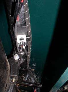
>>"I have added a 3rd brake light just above the license plate light with electronic logic controls of my own design which do not require additional wiring to run from the front of the car. It plugs into the existing harness at the right rear."
So I asked, can you send me your circuit and logic used to do this? I know how to do it with a few relays and some diodes, or some other variations of components that would fit in the palm of your hand. I'm curious to see if you might have a simpler circuit. My circuit logic has up to 1/2 second time delay (half-flash-cycle) in both switch on and switch off for the third brake light, and I'd like to know if you have some logic that could eliminate the delay for switch-on time. This on-delay would be when brakes are applied while one of the turn signals is in the off-portion of the flash cycle.
Chuck then sent this schematic and comments, noting it is free for private use but shall not be used for commercial purpose (without express written consent).
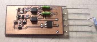
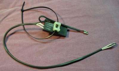
>>"The circuit was built on a SMT PCB and potted. The operation of the third brake light is virtually instantaneous. The circuit operation is as follows:
>>
>>Both power and signal are taken from the two turn signal lamps. Both inputs are fused for protection. IF only one lamp is on, then nothing happens. When both lamps are on then power return is provided for the LED lamp lighting the LEDs. When both lamps are off then the LED lamp is immediately terminated. When both brake and turn signal are active, C1 holds the gate of the power FET up for a period greater than the repetition rate of the turn signal thus keeping the lamp on.
 >>
>>
>>It is limited to about 2 Amps load. I don't know if I would do it the same next time. But it is what I did some years back. It still works. I'll also send a few photos of the finished product.
>>All rights reserved.
 >>My module cannot tell the difference between a turn signal vs a brake and light-off condition of a turn signal. It MUST see two lights on (left and right) at the same time in order to power the 3rd light. Actually, light on is not true. It must see power to the circuit. It is independent of a burned out bulb or a poor bulb connection or bad bulb housing ground.
>>
>>Consider the condition of driving down the road and making a LH turn. Turn on the signal to indicate your intent. The LH turn signal comes on (then off - then on - etc.) This is the 1st indication to the driver behind. Then you downshift and apply the brakes. ~50% of the time, the turn signal light will be on and the 3rd brake light comes on immediately. The other 50% the turn signal light will be off. Apply the brakes and immediately the RH brake light comes on. Up to 1/2 second later the 3rd brake light comes on. This is still better than no 3rd brake light at all. 75% of the applications are less than 250 ms. It takes approximately a quarter of a second for incandescent brake lights to reach 90% brightness.
The main problem with this approch is the circuit board. In very large quantities it would be dirt cheap, but in small quantities it would be prohibitively expensive, and it is virtually impossible for a home hobiest to make one piece. To date only one prototype has been built, and there are no plans to put it into production, so you cannot buy one. The following page gives a diferent approach for a similar circuit made with minitiature relays that you can buy from a local electronics shop.
|