The MGA With An Attitude
FUEL GAUGE REPAIR -- ET-213
Coil Winding
This advanced course is not for the faint of heart or those with functionally fat fingers or jumpy nervous disorder. What you see in the picture is what you have to deal with, small coils of hair size copper wire. Proceed at your own risk. If you are not sure about this, there are professional instrument repair services to save your day. The intent here is to restore burned or broken coils and wire.
Perquisite to this course is the FG-101 course in Construction and Operation of the MGA fuel gauge. Do not even open this instrument until you have read those pages. Disassembly, reassembly, and calibration of this instrument will seem easy compared to working with the coils of hair size wire.
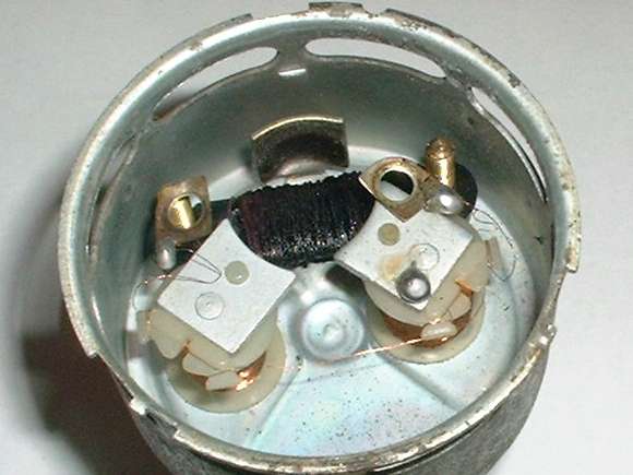
Fuel gauge case with face and armature removed, three coils in place.
At 04:46 PM 1/6/03 -0600, Henri Van Groningen wrote:
>>"I have a problem with my fuel gauge. Working on my restoration of a MGA 1600 I found that the 154 Ohm upper coil is gone and needs to be replaced. My question is can this be replaced with a standard 1/2 watt resistor instead of this coil type resistance?"
No, it carries too much current for that, but it could be replaced with a 2 watt power resistor. The left and right coils are electromagnets that drive the motion of the indicator needle. The top coil is simply a wire would power resistor serving as a shunt.
>>"Alternatively do you have any details how I can redo the upper coil?"
If you have the coil, and it is burned out or broken, you can rewind it. You need to unwind it starting at one end, count the turns, and note the direction of the winding. Then measure the wire diameter with a micrometer accurate to 0.0001 inch increments. I have it recorded as 0.004" for the two side coils, which is spot on for 38-AWG (American Wire Gauge). But this upper coil is different, using alloy resistor wire rather than plain copper.
If you don't have the original coil, you might still make one yourself. The substrate that this coil is wound on is just a piece of phenolic (phenol-fiber), but a Popsicle stick or a thin piece of heat resistant plastic would work as well.
The instrument construction is based on magnetic balance between opposing coils, so when the voltage or current changes the gauge reading does not change much. Using a different size wire changes the resistance and the current, but as long as you get close to the original number of turns on the coil the magnetic balance will be maintained about the same, and it should still have about the same readout. Any small variations can be adjusted out with final setup adjustments (calibration). HOWEVER, ....
[.... BIG SNIP for serious revision ....]
Addendum April 2005:
At 02:46 PM 4/23/05 -0600, Martin from Vancouver BC Canada wrote:
".... I have gotten around to it and look at the visually burned coil. Assuming it is original I have counted 246 turns, the wire measured 16ft6in. ...."
This brings clear the point that this coil is wound with resistance wire. 154ohms/16.5ft gives us the magic number of 9.33 ohms per foot. Different metal alloys will have various conductivity, so you need to have the correct balance between alloy type and wire diameter to closely match the original 9.33 ohms per foot.
Here is a good reference for resistance wire alloys: http://www.mwswire.com/resist1.htm (not found 2/15/15)
Resistance values are listed in Ohms/CMF (Ohms per Circular Mill Foot). This is the equivalent of a wire 0.001 inch diameter and one foot long. A wire 4 mil diameter would have 16 circular mil cross section, and would have 1/16th as much resistance.
To get us started in the ballpark, lets assume the wire is about 4 mill diameter (16 circular mil). To have 9.33 ohm per foot the alloy resistance needs to be about 9.33x16 = 149 Ohm/CMF. Then look for an alloy near to that resistance level, and adjust the wire diameter to yield the desired total resistance. Keep in mind 9.33 ohms/ft.
70% Nickel-Iron might work at 120 oms/CMF (Alloy 120)
(120/9.33)^0.5 = 3.6 mil dia.
With higher resistance you can use a fatter wire.
22% Nickel-Copper is 180 ohms/CMF (Alloy 180)
(180/9.33)^0.5 = 4.4 mil dia.
50% Nickel-Iron is 260 ohms/CMF (Alloy 52)
(260/9.33)^0.5 = 5.3 mil dia.
There are a couple of alloys at 294 ohms/CMF
(294/9.33)^0.5 = 5.6 mil dia.
42% Nickel-Iron is 390 ohms/CMF (Alloy 42)
(390/9.33)^0.5 = 6.5 mil dia.
34AWG = .00630" dia.
35AWG = .00561" dia.
36AWG = .00500" dia.
37AWG = .00445" dia.
38AWG = .00396" dia.
39AWG = .00353" dia.
40AWG = .00314" dia.
Remember that the wire has to have enamel insulation similar to copper magnet wire. Now you can go wire shopping with confidence that you can pick out a suitable resistance wire on the first try.
If you cannot find resistance wire, there may be another solution for this fix. The primary functional requirement here is about 246 turns of wire carrying a certain level of current which is determined by total resistance. So it may serve as well to wind it with plain copper magnet wire, and connect a resistor in series with it at one end. It makes no difference if you do this at the Battery terminal or at the Tank terminal.
100% Copper is 10.37 ohms/CMF (magnet wire)
34AWG = .0063 dia (39.7 circular mil)
10.37/39.7 = 0.26 Ohm/ft or 4.3 ohms for 16.5 ft.
Add a 150 ohm 2 watt resistor in series to control the current. There may be enough space in the bottom of the case to house the resistor, and you could sleeve the leads to have it connected between one of the upper posts and one end of the top coil wire (which would otherwise connect there). The 1.5 watt max heat which was originally generated by the upper coil will now be produced in the new resistor with no change of total heat inside the instrument.
It may also be noted that the upper coil serves primarily as a shunt resistor, and has little or no effect as an electromagnet in this physical configuration. As such, the upper coil could be replaced with a 2 watt 150 ohm power resistor (if you can fit it in the space allowed).
Addendum May 4, 2005:
I have received a sample of the wire removed from the upper resistor coil, thanks to Martin in B.C. Canada. On careful measurement, this wire is 0.0058 inch diameter. Measured resistance is 21 ohms for 28 inches of wire, or 9 ohms per foot. 5.8 squared = 33.64 circular mills. 9x33.64=303 ohms/cir-mil-ft. So the material for the resistance wire needs to have resistance of about 300 ohms per circular-mil-foot.
Consulting the materials chart here: http://www.mwswire.com/resist1.htm (not found 2/15/14),
the following materials are close:
| Material code | Material Content | Resistance |
| MWS-294 | 55 Cu, 45 Ni | 294 ohm/cir-mil-ft |
| MWS-294R | 29 Ni, 17 Co, 54 Fe | 294 ohm/cir-mil-ft |
| Manganin | 13 Mn, 4 Ni, 83 Cu | 290 ohm/cir-mil-ft |
It appears that 48 Ni, 52 Fe might also be very close to 300 ohm/cir-mil-ft, if such an alloy was available as resistance wire.
It also strikes me that you could use a wire slightly larger in diameter if it has higher resistance. For instance, Alloy 42 with 42% Nickle-Iron content is 390 ohms/cir-mil-ft. To have 9 ohm/ft you need 360/9=40 circular mil, or 0.0063 inch diameter.
Now we can go resistance wire hunting.
http://www.mwswire.com/resist1.htm (bot foune 2/15/14) - Resistance alloy properties
http://www.mwswire.com/resist3.htm - Resistance wire data - (not found 2/15/14)
http://www.mwswire.com/resist2.htm - Trade name cross reference - (not found 2/15/14)
http://www.mwswire.com/insspec.htm - Insulation specification codes - (not found 2/15/14)
Addendum June 18, 2005:
Someone has bitten the bullet and special ordered some of this wire with enamel coating (at significant expense). If you need enough to do a single coil repair, Robert K. Jeffers <bobj20@adelphia.net> has offered to supply it for $0.70-USD per foot plus postage. This is #31 NiCrc+HML wire that is close to the calculated 9.33 ohms/foot.
Addendum August 31, 2005:
At 04:39 PM 8/29/05 -0700, Martin Sharpey wrote:
"Take the front plate off and remove the resistor coil by breaking it in pieces and removing as much wire as you can. Take care not to cut the thin wire between magnet coils. Close it up. Put the resistor outside where you connect the wires. Done!"
This does work, if you don't mind the resistor being exposed on the back if the instrument. It requires a 150 ohm 2 watt resistor. Do be careful not to short the resistor wires on the mounting bracket, illumination lamp, or any other wires in the vicinity.
At 03:10 PM 8/31/05 -0700, Martin Sharpey wrote:
"My 2 watt resistor is only 5/8 inch and fits nicely between posts. No danger to short out."
|