The MGA With An Attitude
FLASH TO PASS (headlight flasher) Switch - AT-113
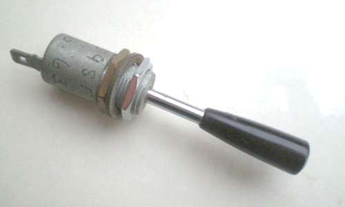
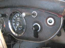
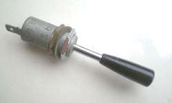
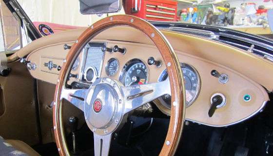
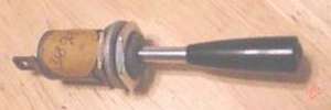 This is an original optional accessory part for the MGA. Bump that bat handle 10 degrees in any direction and this switch makes a ground contact. This was used with a relay and a small wiring sub harness to allow the MGA headlights to "flash to pass". For factory installation the dash was commonly drilled to mount this switch just above the turn signal switch. For aftermarket owner or dealer installation it could have been located just about anywhere in the dash, but commonly a finger's reach from the steering wheel.
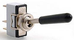
Since original style Lucas bat switches are now so rare, you can use the one shown here. It is spring loaded one direction; mount it either side up. See Holden part no. 020.145
The related relay may have been screwed to the firewall or high on the kick panel behind the dash.
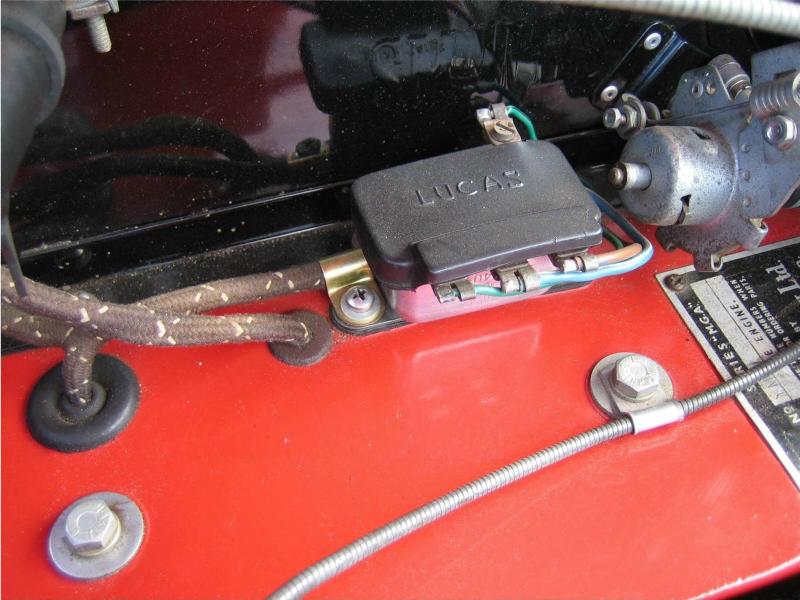
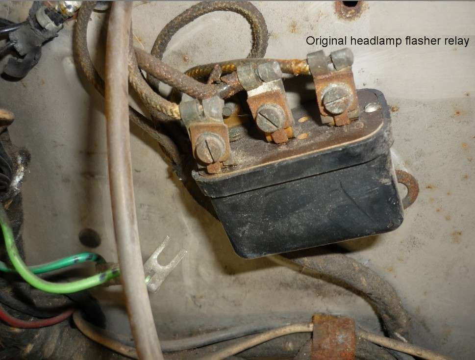
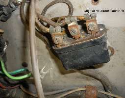
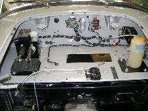
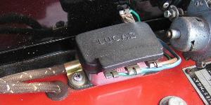 If you believe the SPL illustration (below), the factory would have mounted it on the heater shelf near where the harness branch goes to the foot switch. This picture shows it mounted in front of the heater box on a Twin Cam car. Interesting to see it has the rubber cover (not listed separately in the SPL) to protect most of the hot terminal bars on the relay.
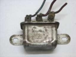
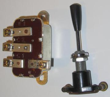
The original type switch is Lucas 23A, part number 31898 or 31898A.
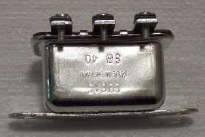
The relay is Lucas SB40/1, part number 33135 or 33169.
There must be a small wiring sub-harness as part of the installation kit (as in the photo above), but this is not listed in the SPL, and the assembly is not listed as a kit.
     From the Lucas parts list:
     Model SB40/1 = Single bobbin, 2-hole strap fixing.
     All listed here are 12-volt, 4-terminal
     (but not sure terminal arrangement is the same).
  PART    SPECIAL FEATURES			USE WITH
 33135B   4-terminals				W.T. horns
 33157A   4-terminals marked C1, C2, W1 and W2  Cover marked
 33229A   4-terminals
The relay needs an always hot power wire from control box A1 so it can work when headlamps are off. The relay needs a wire going to the high beam circuit (probably on the foot switch high beam terminal). It needs a wire going to the dash switch to be switched to ground to actuate the relay. The fourth wire is a low power feed from the fuse box A4 terminal, so the circuit will only work when the ignition switch is on.
The SPL has these part numbers listed (all items marked "Optional Extra"):
45 - BHA4116 - Switch, headlamp flasher (N. America)
46 - 3H1911 - Relay, headlamp flasher (N. America)
47 - PMZ0308 - Screw fixing relay (2 req'd)
48 - FNZ103 - Nut for Screw
49 - LWZ203 - Washer for nut (spring)
Alternate prototype parts.
This is a composite of the Flash To Pass circuit diagram as shown in the 1600 and Twin Cam workshop manuals. The primary power for this circuit is a 16 gauge brown/blue wire from control box A1 to relay C1. The reason it draws power from the control box terminal is because it will pull an extra 10 amps to light the high beams while the low beams are still on, not wanting to add this load to the same wire that is supplying the ignition switch and lighting switch.
Relay power output from C2 goes to the high beam circuit. This can connect at either end of the blue/white wire running from the dipper switch to the twin tube snap connector at RF corner of the car. Relay W1 gets a green wire from the fused ignition circuit. This is a low current wire, so it can connect to fuse block A3 or to the back of the fuel gauge (if relay is mounted behind the dash). The grounding signal wire from relay W2 must run to the new dash switch. Being switched to ground it should be black with a stripe. A blue stripe would be appropriate (although it is not labeled on the schematic). If the dash switch is not grounded directly on the dash panel, then it will need a black grounding wire from the switch to the back of one of the instruments (where it can connect to another black harness wire).
Addendum November 2011:
On 09 Nov, 2011, the two pieces shown below sold on ebay.co.uk for 74.99-BPS ($119.47 USD). In Aug and Sep prior, identical relays described as "Austin Healey overdrive relay" sold on ebay.co.uk for 24.50 and 23.50. (The original switch then might be worth about 50.00 these days).

The auction description was as follows:
 MGA FLASH TO PASS (headlight flasher) Switch + Relay MGA FLASH TO PASS (headlight flasher) Switch + Relay
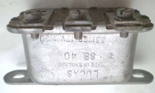
This is an original extremely rare optional accessory part for all MGA models including the Twin -Cam. The part no. is marked as 31898A and is in extremely good condition. Included is a period Lucas SB 40 relay date stamped 1-58. I have not tested this relay but I obtained it from Peter Wood, so have no reason to believe that it will not work. The switch, ordered as a Factory option, will have been mounted just above the turn signal switch. Such as on the Twin Cam prototype PJB 147. A really nice job of installing this optional accessory will be achieved by having a small wiring sub-harness cloth covered braiding made up. Or you could use contemporary wiring!
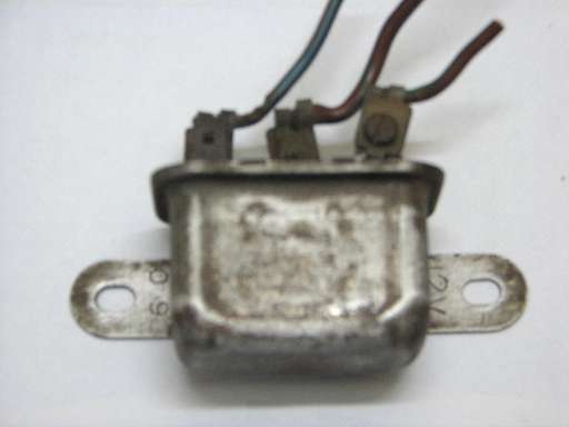
Below left, thought to be an original relay from a late MGA 1600-MK-II, July 1961 production date. This is the first one I've see with the plastic case.
Below right, a recent production relay being sold via eBay. Close, but not quite concours, missing the small numbers near the flange.
Now brace yourself. In March 2012 this New Old Stock, original Lucas 23A (31898A) switch sold for a whopping 201.53-GBP, $319.70-USD. For that it merits a larger picture.
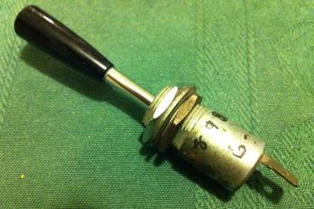
This FTP switch with screw post terminals may be a Wipac switch.
On 7/23/2017, Dominic Clancy wrote:
"A result of rewiring and sorting out a friend's car and trying to get the flash to pass system working again after the original relay fell apart. The relay has to be one with C1/C2/W1/W2 markings. The image below is taken from the Lucas manual and correctly lists the configuration of each of the relay types. There are some 6RA relays that have the correct pin configuration, but the later 6RA numbering scheme is different and under the new numbering schemes the relevant suitable relays appear to be SRB121, SRB111, SRB113.
 The only available reproduction SB40/1 relays are all C2/C3 and don't work with the standard wiring setup placing the C1 connection at C3. The only source I found listing the correct terminals delivered me a C2/C3 item which we have tried but doesn't work. It looks as if I am going to have to use 6RA innards and epoxy them into the casing of the old SB40. The only available reproduction SB40/1 relays are all C2/C3 and don't work with the standard wiring setup placing the C1 connection at C3. The only source I found listing the correct terminals delivered me a C2/C3 item which we have tried but doesn't work. It looks as if I am going to have to use 6RA innards and epoxy them into the casing of the old SB40.
The correctly wrapped and colored harness is available from Autosparks in the UK -- HEADLAMP FLASH HARNESS - MGA 1600 -- SKU: 5951".
Addendum January 22, 2018:
Mark Hester in Australia wrote:
"The flash to pass relay does not live in the engine bay but under the dash. I found two spare tiny holes which match exactly the Lucas relay. The problem is though, the lower screw threads would rub on the wiring harness, so I will fit a tiny hex bolt from the engine bay side. Easily missed these holes as they are behind the master cylinders. I certainly don't have holes in front of the heater for the relay".
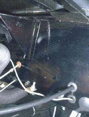
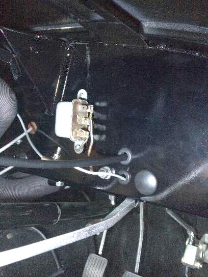
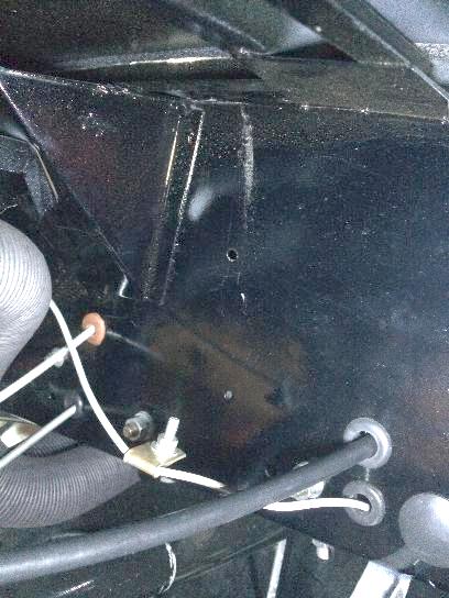
On the left, relay mounted behind the dash (right hand drive car). Center photo, relay removed to show the mounting holes. On the right, in the engine bay where the mounting screws for the relay are located behind the Twin Cam master cylinders.
This is the pre-production Twin Cam PJB147 (c)YDL/14/499, so the relay and/or location may not be representative of production cars, or dealer or customer installed parts. The FTP option was apparently seldom a factory installation, so the holes may have always been hand drilled, and the relay location could vary.
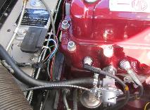
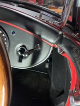
 On Jan 27, 2018, Mark Wellard in Brisbane, QLD, Australia wrote: "The attached shows a late deluxe car with the factory position".
This could only work for 1600 or 1600-MK-II cars, because that position is occupied by the turn signal relay on the 1500 cars. Also it would only be installed there in a "heater delete" 1600, because it would be difficult to drill the mounting holes behind the heater box.
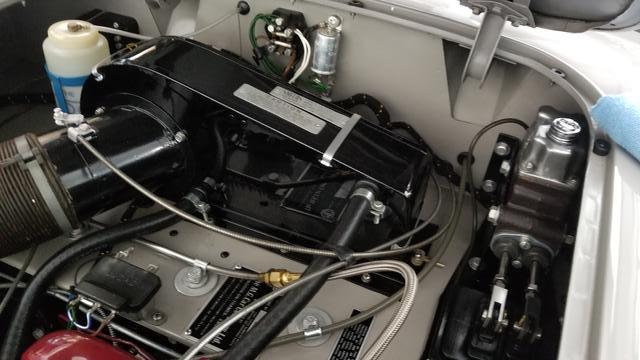
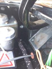
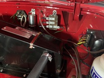
For another location, here is a relay mounted at the front of the heater shelf. This
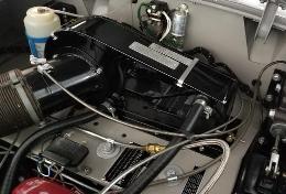 makes it easy to drill clearance holes in the overhanging edge, and install the hex nuts underneath, but it also puts the relay close to the engine valve cover. You may also notice two rubber plugs farther back between the fuel pipe and heater box, which appear to be the same distance apart to match the relay size. These holes would be aft of the frame goal post where they may also be drilled through with nuts underneath. You can compare this with a photo near top of page (with red paint) with the relay installed in the more rearward location (happens to be a Twin Cam heater box). I suspect that would be a more common location for factory installation.
 Addendum February 18, 2019:
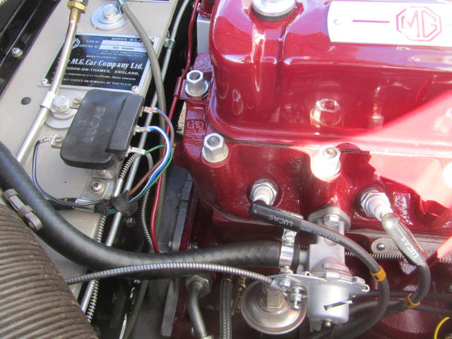
Here is another one in the same position. It is worthy to note that with the heater installed in the pushrod engined car the lower (input) heater hose blocks some space to prevent mounting the FTP relay in the factory holes directly in front of the heater box. The relay can be installed in that location in the Twin Cam with reversed heater.
You may realize by now that this is an accessory part. It could have been installed at the factory on special order. Otherwise it was commonly a dealer installed option, or aftermarket owner installed. While the electrical circuit is well documented, the mechanical installation was badly neglected in factory literature. If you bought the factory kit, it would likely have included installation instructions, which may or may not have had illustrations for the component locations. The instructions may have been more generic, possibly not specific for MGA. Unfortunately I have never seen that instruction sheet (if there ever was one). So we may never know unless someone might find an unopened New Old Stock kit still sitting on a shelf somewhere.
The "kit" would also have included a small wiring sub-harness, as these wires are not woven into the original wiring harness. That FTP sub-harness is also not physically documented (aside from the schematic). It should have been specific for MGA, to have the matching woven cloth cover. Physical location for the relay may have been influenced by length of the supplied sub-harness branches.
Addendum January 27, 2022:
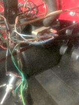
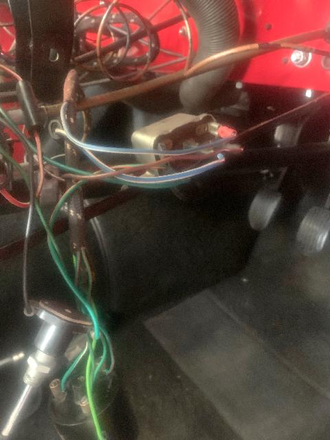
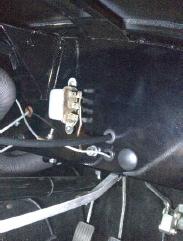
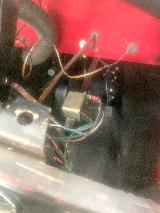 Here is another installation from Dr. Frans Henskens in Australia. This was installed in Twin Cam with chassis number 700 (Sept 1958), thought to be factory installed, but looking a lot like aftermarket (no wiring braid covered sub-harness and crimp-on Lucar connectors). I post this as alternative example, as the relay is attached to the under dash brace.
AddendumOctober 31, 2024:
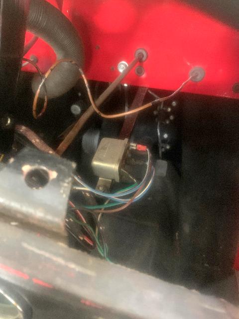
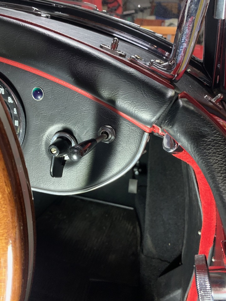
Here is another one well documented, a 1962 MGA 1600-MK-II "Deluxe" with factory installed Flash-To-Pass option.
On10/31/2024, Dr. Frans Henskens >!-enskens@henskens.com.au-> in Australia wrote:
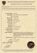
"I have now completed importation of my 1600 MkII De-Luxe from the UK (chassis GHN2/106369, original registration 793WAE) to Australia. As per the Heritage Certificate it had FTP installed from the factory. The FTP had been removed by a PO, but the hole was still present in the dash, behind the leatherette covering which was apparently re-done during restoration in the late 1970s. I can possibly see why the PO removed it - the switch in the MkII position is easy to knock, gets in the road while trying to operate the indicators, and I suspect would be pretty easy to break with one's knee while getting into or out of the car.
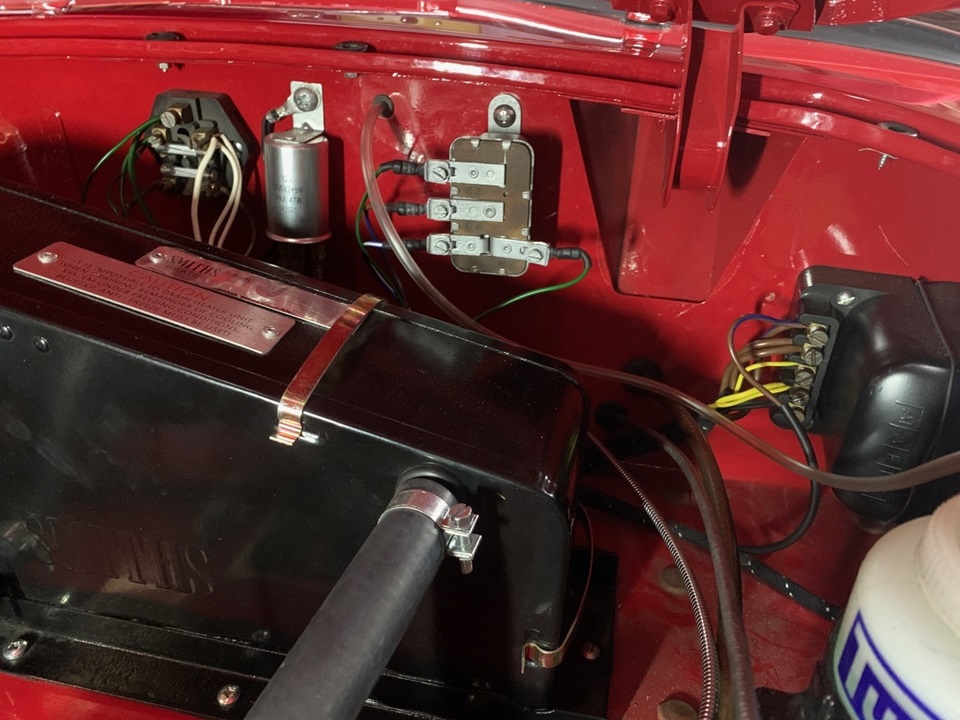
I've managed to source a used SB40/1 relay, used your advice to purchase a harness from Autosparks in the UK, and found a switch with 4" stalk which we shortened and re-threaded to the appropriate 2". As per your 2018 picture from Mark Wellard my car had the holes in the firewall beside the flasher unit".
|