The MGA With An Attitude
Electric POWER STEERING for MGA #2 - SR-302
On 2/19/2018, Dominic Clancy wrote:
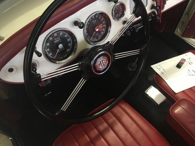
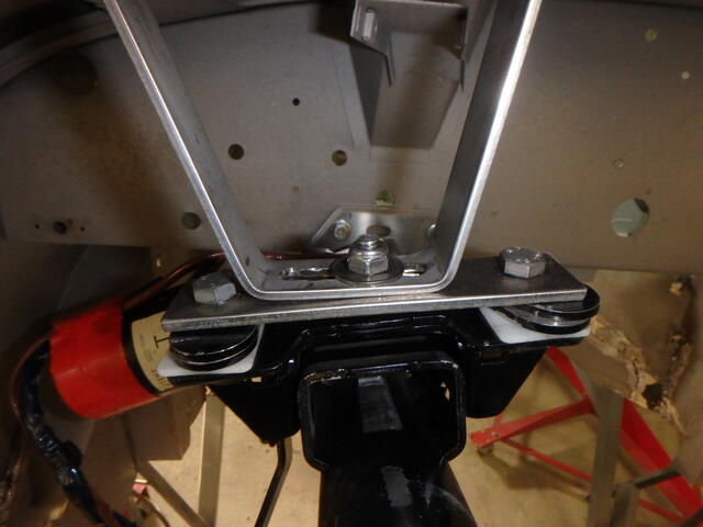
"Heres a new electric power steering. Basis is the steering column from a Toyota Yaris 2004. Its a unit that has a fail-safe mode which is stimulated by current to the VSS pin on the ECU, so it works without a VSS sensor. The unit is a bolt in replacement for the standard column, and no welding or drilling is required. Supplier is Gio Delicio in Germany. The old column is removed, and only the lower clamp and steering wheel are re-used. The upper mount is replaced by a welded stainless frame that screws to the original body mount.
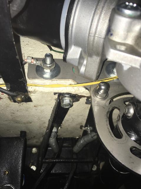
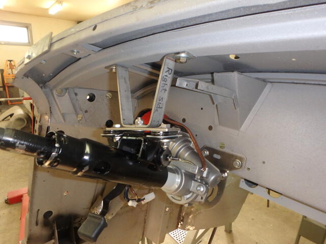
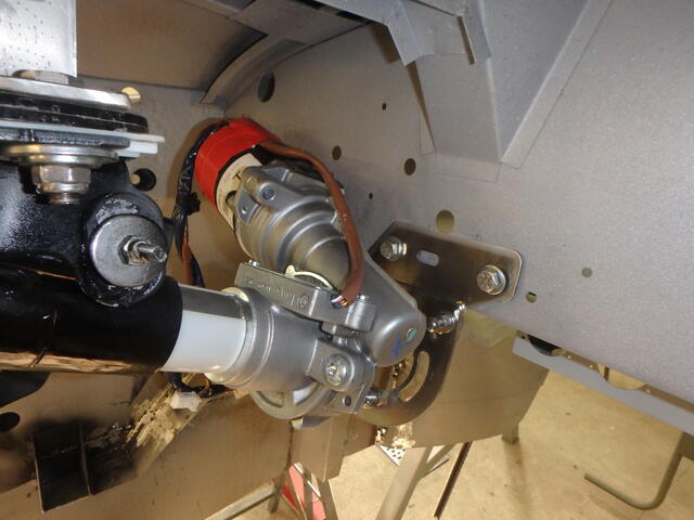
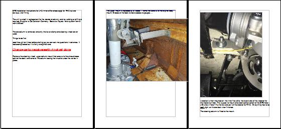
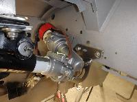
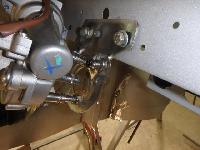
A bracket is then mounted on the inner firewall to the lower bolts of the bracket for the master cylinder. This is used to mount and stabilize the bottom of the EPS motor. Adjustment to individual cars is achieved here by cutting the bolt and reinforcing sleeve to length between the bracket and the threaded motor mounting lugs. The bracket is slotted to take up dimensional variations and center the Toyota knuckle in the bracket and to allow the motor to be clocked out of the way.


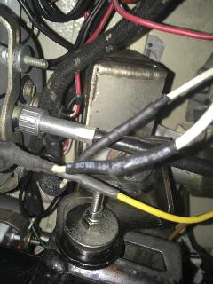
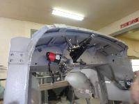
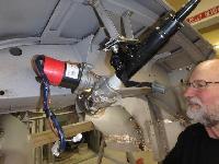
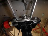
 The upper part of the column bolts to the lower part of the stainless frame, using the original Toyota mounts. The ECU is also mounted to this frame, sitting behind the tacho and speedo. The Toyota column has the bits and cams for indicator stalks, light switches etc. removed, and the sliding piece from a MGA adjustable column welded and pinned to replace the Toyota end. The EPS motor sits in the space between the hood release handle and the tacho / speedo cables.
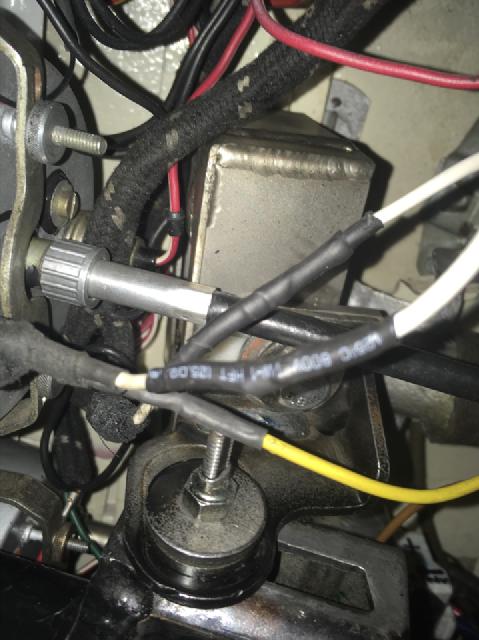
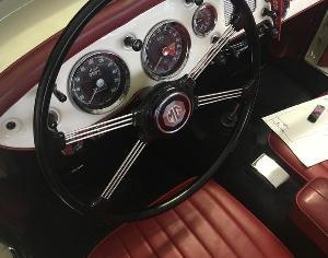
Wiring is simple. Motor: A permanent live feed to regulator (fused at 40A), ground to the master cylinder bracket. ECU: Switched to live at ignition terminal on fuse box, and grounded through casing. A potentiometer is provided to adjust steering assistance to the VSS terminal on the ECU. Appearance from the drivers seat is the same as for a standard non-adjustable column. Its standard in the engine bay, and can only be seen by sticking your head under the dashboard. It is a very tight but very well engineered solution. The unit activates about five seconds after turning the key, so once the car is started, its active. There was no need to adjust or re-calibrate the torque sensor on the EPS.
I am looking at the final step of making it fully automatic and speed sensitive by adding a VSS signal. I have all the parameters, I just need someone to do the programming. Theres a similar VSS unit for the Opel Corsa EPS (thats the basis of the Easysteer kits), but the Yaris EPS is available around the world, but it doesnt work with the Yaris ECU. It needs a signal from a hall effect sensor at the front of the propshaft), something like this:
http://www.motorsportsinnovations.com/Holley/holley-efi-sensors.html
Or a tag on a prop shaft bolt to produce a mappable signal to match and produce the VSS signal on the Yaris EPS Controller ECU pinning (D31 is where the potentiometer is currently connected, I'd like to replace this with the Variable VSS signal). This next link is the full manual for the Yaris power steering (3.8-MB 97-page tech manual).
SIGNAL DESCRIPTION
Since my 1/10 post I did a little more testing with a real square wave for the VSS signal. My square wave generator will not allow me to vary the frequency without stopping the output then restarting at the new frequency so I really could not tell at what frequency the assist level changes but did find out something I did not know and have never seen mentioned before. I was expecting the output torque to change based on the VSS frequency and it does but the new thing I found is the Yaris unit also changes the damping on the input shaft as the VSS frequency goes up.
 At 2 Hz (the minimum turn on frequency) the input spins the unloaded output with no resistance and when the output is loaded with a spring scale I get around 60LBS with about 6LBS input. At 2 Hz (the minimum turn on frequency) the input spins the unloaded output with no resistance and when the output is loaded with a spring scale I get around 60LBS with about 6LBS input.
With 30Hz on the VSS the input spins the unloaded output but is lightly dampened in movement about 15 degrees either way from center (where you would make corrections to stay in lane) but becomes totally free if you jerk the wheel like in an emergency move. When the output is loaded with a spring scale I get around 48LBS with about 6LBS input.
With 60Hz on the VSS the input spins the unloaded output but is more heavily dampened in movement about 15 degrees either way from center (where you would make corrections to stay in lane) but becomes totally free if you jerk the wheel like in an emergency move. When the output is loaded with a spring scale I get around 40LBS with about 6LBS input.
So it appears to have 3 power levels and 3 dampening levels (none, light and heavy).
On October 14, 2018, Dominic Clancy wrote:
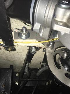
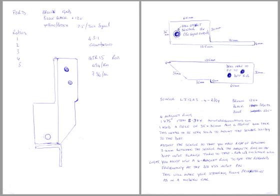
"I have worked out how to generate the VSS signal work for the Yaris unit. It requires a four-magnet ring and a simple sensor. I plan to mount these to the rear differential input pinion. This generates exactly the frequencies required by the Yaris control box at various speeds to make the power steering speed dependent, which has to receive the signal on pin 7 of the connector. -- I am now starting to assemble the parts for a trial on this. The most expensive part has to come from the USA, and the shipping is a complete rip-off".
Addendum July 1, 2020:
We have some additional information from Dominic Clancy.
"With the renewed interest in the system I have updated my fitting instructions and added some pictures of the revised mounting. Colyn Firth has made a good wiring diagram, and I also attached pictures and sources of the parts not yet provided by Gio".
Click for 12-page installation instructions (5.7-MB file)
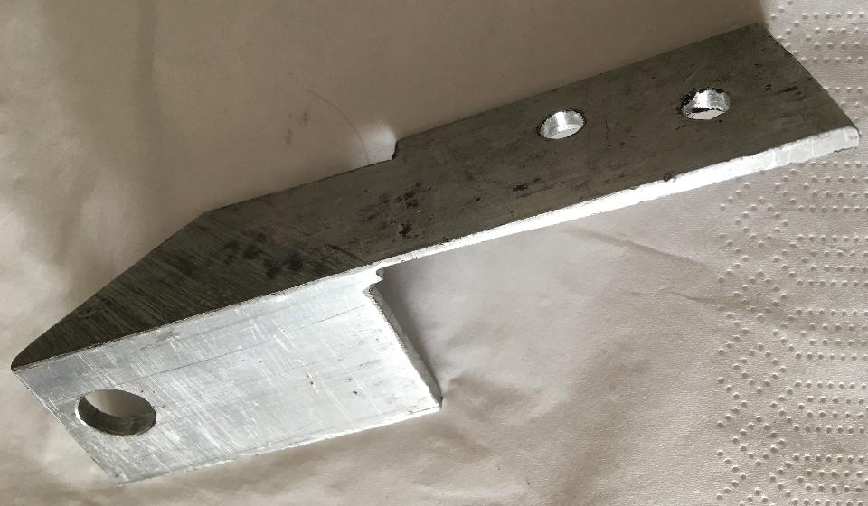
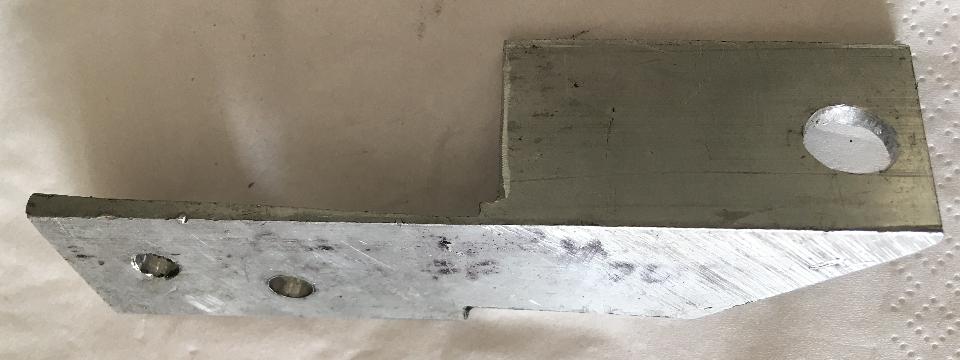
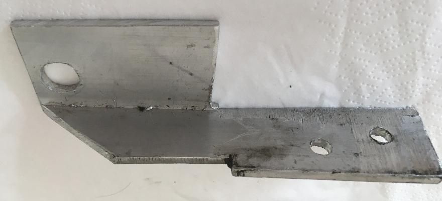
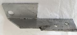
Click for 2-page Steering Sensor Bracket drawing
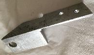
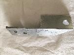
Some photos to go with the drawing
Click for EPS wiring diagram.

Following is the full effective working sequence:
When main supply is connected nothing occurs. (Car stored)
Then (when ignition is switched on) positive is connected to D32/6 this activates ECU within 5 seconds (double click heard in ECU).
When rotation signal is coming from axle sensor (4 pulses at minimal) to D32/5, this activates EPS motor. And the system remains active even when no more rotation signals comes in. Variable pulse frequency gives variable steering power and damping of the EPS.
When ignition positive (D32/6) disappears (engine switched off) a relay is activated in ECU (single click and 220 mA drain) during exactly 120 seconds in order to maintain the ECU active if, eg after an engine stall, the starter motor is solicited for starting engine again, so EPS is active immediately.
120 seconds after switching off engine ignition the relay in the ECU falls (single click) and system becomes totally inactive as it was before using the car. No more drain on the battery.
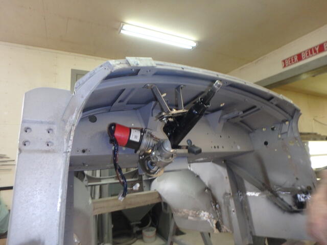
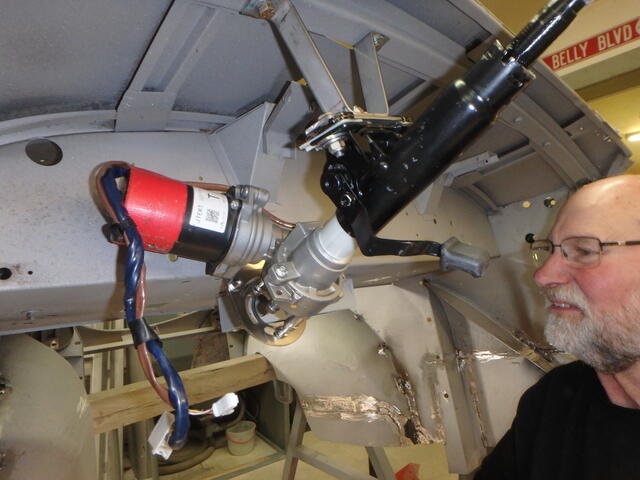
Addendum March 24, 2021:
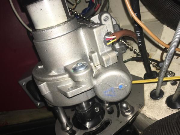
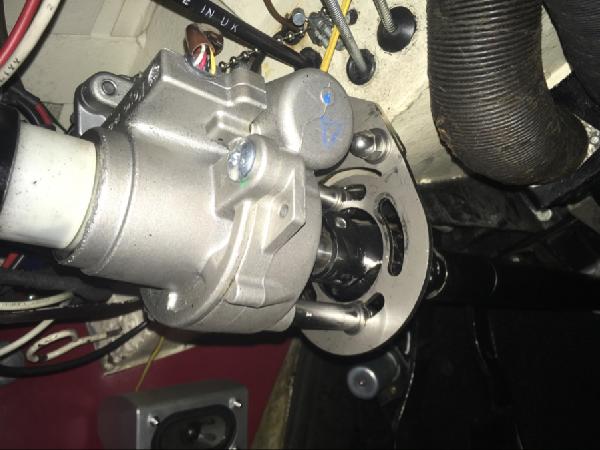
More pictures of a Yaris derived unit from Gio installed in March 2021 by Brian Woods in Westbank, BC, Canada. Very clear pictures in an empty body shell.

Addendum May 21, 2021:
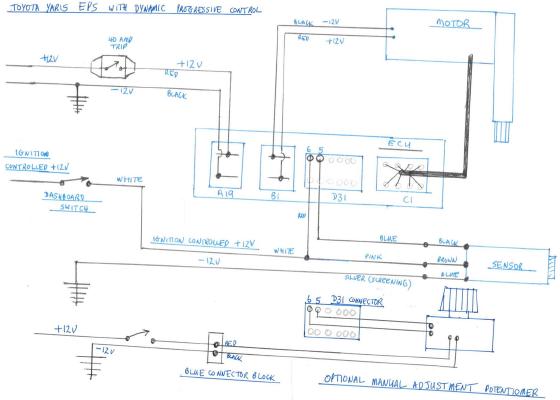
Another wiring digram, compliments of Colyn Firth in South Yorkshire, UK. This one includes both the speed sensor and manually variable assist control, but for pre-ABS cars. This may not be correct for steering units from cars originlly equiped with ABS.
Click for EPS wiring diagram with variable power assist control (pre-ABS type)
|