The MGA With An Attitude
IGNITION COIL POLARITY - IG-104
There is some misconception about ignition coil polarity and how important it may be (or not). For most people it is only a matter of lack of knowledge, perhaps followed by getting some bad information. How the coil works (with points and condenser) to create a high voltage spark is covered in another article. This article is a discussion about electrical polarity of the coil and spark plugs.
  The ignition coil is essentially a low voltage to high voltage transformer with about 100 to 1 ratio of windings and voltage. The coil case is not grounded, and both primary and secondary windings inside are "floating" or isolated from the case. The only thing the windings have in common is one end connected to the same primary terminal, and it really doesn't matter much which one. Being a transformer it must have pulsating or alternating current to work. Initial pulsating is done by connecting and disconnecting the primary circuit ground connection. Alternating current then comes into the function in a big way by electrical "ringing" in the condenser at very high frequency. A transformer is not affected by polarity, since it is an alternating current device, so it matters not to the transformer what the input or output polarity may be. Any polarity on the primary side and any polarity on high tension side will produce the same quality of spark.
Why then do we worry about coil polarity? Because the spark plugs do care which way the electrons are flowing in the high tension circuit. The spark plug has a thermally insulated center electrode (surrounded by ceramic). With engine running the center electrode runs substantially hotter than the exposed end electrode. Design of the ceramic insulator determines how hot the center electrode will run, leading to the designation of hotter or colder spark plugs. As electrons go, they love to jump away from a hot surface and fly toward a colder surface, so it is easier to drive them from hot to cold rather than from cold to hot. End result is a difference of 15 to 30 percent in voltage required to make spark "initially" jump the gap on the plug depending on which way it is going. So the spark plug prefers to see a voltage potential that is negative on the center electrode and positive on the end electrode for the very first hop of the spark. Oddly enough, this has nothing to do with polarity of the vehicle electrical system, but it is influenced by the common connection inside the ignition coil.
The common knowledge bit about electrons is that they carry a negative charge. For electrical bits (similar to magnetic bits) opposites attract each other and negatives repel. This means the direction of flow of electrons in a car is from the battery negative post through the wiring to the battery positive post (not necessarily intuitive). If you reverse cable connections on the battery the current flows in the opposite direction through the vehicle wiring. For most original functions on the MGA this matters not one whit to anything, as most original equipment in the MGA is not polarity sensitive (except maybe the optional radio). As one end of the primary winding in the ignition coil is connected to one end of the secondary winding, reversing polarity of the coil primary side will reverse the drive direction of the spark current on the output side (even though current in the vehicle low voltage wiring still flows the same way).
So reversing vehicle electrical system polarity will reverse direction of spark drive. The engine still runs either way, but spark might be more reliable under marginal conditions if you get it right. The simple fix for this is to reverse the two primary wire connections on the ignition coil. Because the output spark is very much higher voltage (20,000v) than the car battery (12v), it doesn't care if the battery polarity is helping or hindering by a meager 12 to 14 volts in battery potential.
So how do we know which way to connect the ignition coil for best results? Original production coils were generally marked on the primary terminals "SW" for Switch and "CB" for Contact Breaker. This was assuming the vehicle wiring was connected for positive earth (positive battery cable grounded on the chassis). If you reverse battery polarity (going to negative earth), then these coils need to be connected with "CB" to the ignition switch and "SW" to the distributor points wire. Later issue ignition coils are marked "+" and "-" on the primary terminals. These are more no-brainers, as you only need to match the terminal markings to the battery posts. For positive ground the "+" terminal goes to the distributor (to be grounded on the engine block). For negative ground the "-" terminal goes to the distributor (to be grounded on the engine block).
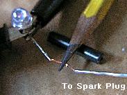
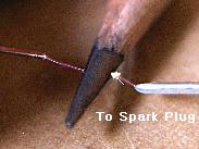
 If you are still skeptical about all this, there is a quick way to check directly which way the current is flowing in the high tension circuit. Disconnect a spark wire from a spark plug (or the coil wire from the distributor cap). Hold this HT wire near a grounding point (or near the connector end of a spark plug), and position the tip of a graphite pencil in between. When you crank the engine (no need to start or run) you can observe the resulting spark jump between wire and pencil, and between pencil and ground (or spark plug). A flare (hard to see) toward the plug (or ground) shows correct polarity while a flare toward the coil shows reversed polarity. If the flare goes toward the coil, just switch the primary wires on the coil and make note of the connections for future reference.
 Can't see the flare? Not sure yet? You can also check spark polarity using an analog (moving needle) volt meter. Hook up a voltmeter with the negative lead to the plug terminal and the positive lead to the block. Set the meter on the highest volt range. Crank the engine over (no need to start it), and you should see an upward swing of the voltmeter needle (don't be concerned with taking a reading). If the needle swings down off the scale, your coil is hooked up wrong. To correct it reverse coil primary leads. Do not worry about the coil markings, but make note of them for future reference.
Addendum:
On 12/14/2017, Curt Allen wrote:
"I've been playing with a spark-generating circuit for fun, and decided to replicate your test with a pencil lead. It worked and the "flare" was visible! I took some pictures (very challenging to get good ones)".
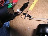
"Note that an LED is in series with the spark gap! Apparently the spark current is either too low or too brief to blow it up; it gives a nice red flash with each spark. Its presence helps to verify that with the current circuit connections the HV lead goes positive, and that conventional current (ignoring electrons) flows from the positive on the right, through the spark gaps, the pencil lead, and the LED to the negative on the left at one of the coil terminals".
|