The MGA With An Attitude
How The INTERLOCK ARM Works - GT-110B
In the illustration at right, part 114 is the Remote Control Shaft inside the gearbox rear extension (which is
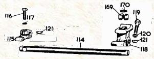 shown on the previous page). As the hand shift lever is moved left and right, Front Selector Lever 115 moves up and down. As the hand shift lever is moved fore and aft, lever 115 moves aft and forward. This lever is choosing one of the Selectors that are attached to the three Shift Rods, and in turn moving one of the shift rods fore and aft. There is an Interlock Arm interfacing between the selector lever and the selector slots to hold two shift rods in neutral position while a third rod moves to engage the selected gear. This arrangement prevents engaging two gears at once.
Items 62 and 63 are Ball and Spring, three of each. Item 64 is Block, shift rod aligning, attached to the rear face
 of the main gear case. A spring is pushed down into a blind hole in the block, followed by a ball. This ball and spring are to be depressed using a thin assembly tool punch while the shift rod is inserted through the block. When the shift rod hits the assembly punch, the punch can be withdrawn to allow the rod to pass through the block. The spring and ball are then trapped in the blind hole behind the rod. As the rod moves to the intended position, the detent ball can drop into a notch in the rod to secure the rod in place, preventing any further motion. Items 47 ,51, 56 are shifting forks for Reverse, 10-2, and 3-4 respectively. These will be pushed fore and aft by the shift rods.
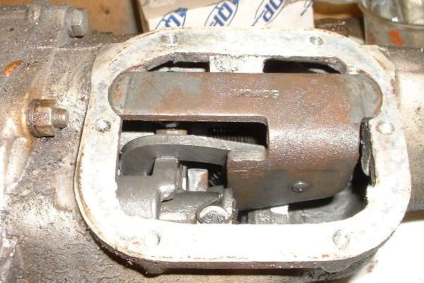
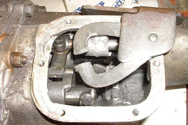
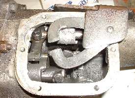
The shifting rods and forks will be pushing reverse gear and the sliding hubs. it is of course important not to engage two gears at once. It is the function of the interlock arm to hold two of the selector gates in neutral position while a third selector and rod will be moving.
When the hand shift lever is actuated the linkage train in the remote shift extension moves the selector rod inside the rear housing (first illustration at top of page). The front end of the remote control rod holds the selector lever. The output and of the selector lever moves up/down when choosing a selector gate, then fore/aft to move the selected shift rod. The output and of the selector lever is also nested in the open center slot of the interlock arm, so the arm moves up/down with the selector lever. When the selector lever pushes a selector gate and shift rod, the lever moves out of the interlock arm while keys on the selector gate move into the space in the arm to hold the interlock arm in place until the selector lever returns back to the neutral position.
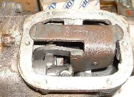
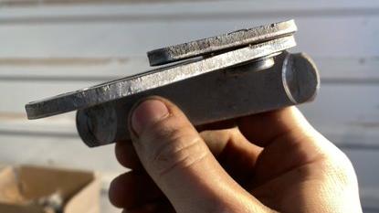 Picture here shows the edge view of the interlock arm assembly. It has curved spring washer (shim) in between the moving arm and frame to provide some friction and anti-rattle function. The pivot shaft is a shoulder rivet. Sometimes the rivet may work loose allowing the arm to wobble a bit, and the resulting misalignment can cause shifting problems, like jamming in gear or preventing selection of a desired gear from neutral.
 There is a factory Confidential Service Memorandum detailing a field fix for this problem. There is a factory Confidential Service Memorandum detailing a field fix for this problem.
MG-269 - Jamming In Gear (csm)
Also see Reverse Gear Lockout and How It Works and
Detents for the Shift Rods and Sliding Hubs.
|