The MGA With An Attitude
WIPERS TWO SPEED DR3, With A Few Modifications -- ET-219H
DR3 Two Speed Wiper Motor - by David Adams
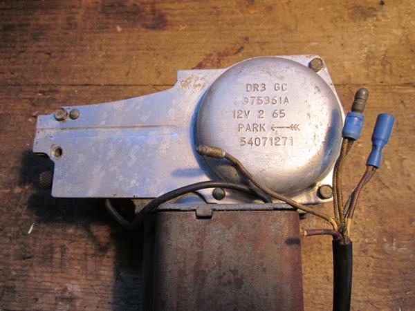
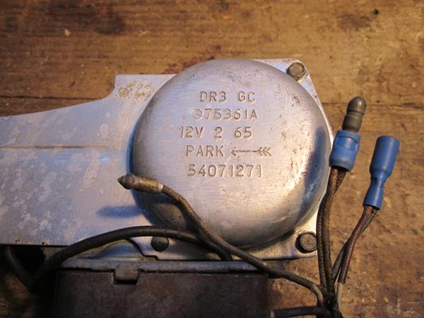
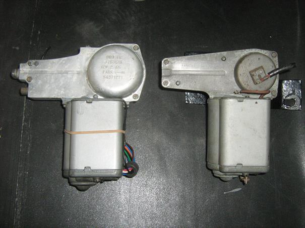
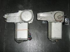
The DR3 wiper motor resembles the DR2 in that the motor end is the same size as the DR2 but the gear-wheel and its housing are larger. There are no terminals on the end cover, apart from the motor earth, and a bundle of wires emerges from the joint between the end cover and the housing, 5 or 6 depending on the model.
It is fixed by the same three studs on the same centres into rubber bushes in the mounting plate and it will fit the existing plate. However, the centreline of the gearwheel and of the fixing studs has been moved 10mm further away from motor end to accommodate the larger gear wheel.
|
|
|
|
|
Comparison of Lucas Wiper Motors DR2 Versus DR3
 All Dimensions in Inches, Resistances in Ohms All Dimensions in Inches, Resistances in Ohms
DR2 75297FDR3 75361A |
Journal Brush End Diameter |
0.25 |
|
0.25 |
|
Journal Brush End Length |
0.50 |
|
0.562 |
|
Journal Gearbox End Diameter |
0.384 |
|
0.384 |
|
Journal Gearbox End Length |
0.875 |
|
0.875 |
|
| Insulating Sleeve on Long Bolts |
No |
|
Yes |
|
Commutator Diameter |
0.760 |
|
0.762 |
|
Commutator Length |
0.531 |
|
0.531 |
|
Worm TPI |
8 |
|
10 |
|
Armature Segment Diameter |
1.625 |
|
1.625 |
|
Armature Segment Length |
1.312 |
|
1.312 |
|
Armature Segments |
10 |
|
10 |
|
Armature Length Overall |
5.182 |
|
6.50 |
|
Motor Case Length |
3.125 |
|
3.125 |
|
Resistance Field |
1.2 |
|
8.5 |
|
Resistance Resistor |
NA |
|
10 |
|
Resistance Across Armature Segments |
1.2 |
|
1.2 |
|
Resistance Segment to Segment on Commutator |
0.7 to 1.1 |
|
0.7 to 1.0 |
|
Resistance Segment to Segment on Laminations |
0.5 |
|
0.5 |
|


When you take the cover off, wash the crank pin fixings with solvent and mark the position of the wash-er under the spring with respect to the double D on the crank pin. Someone on a Jaguar blog wrote that this assembly is almost impossible to reassemble correctly, so be warned.
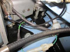
A description of the construction and functioning of the DR3 is shown in ET-219D. This item is con-cerned with adapting the DR3 to a RHD MGA. Due to the presence of the master cylinder adjacent to the wiper motor on LHD cars fitting of the DR3 may be more difficult.
Wiring
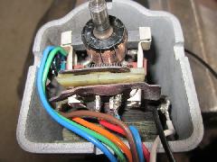
The original wires, 14/0.010, were in poor condition with insulation perished and copper conductors showing through. These were replaced with 32/0.2, 1.0mm2 thin wall cable replicating the original col-our code.
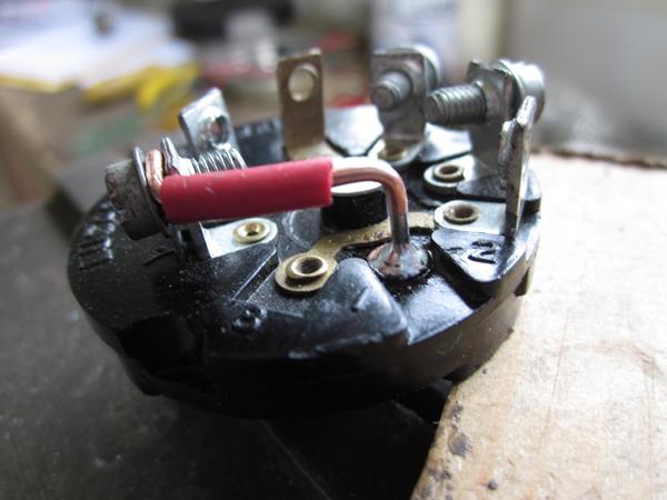
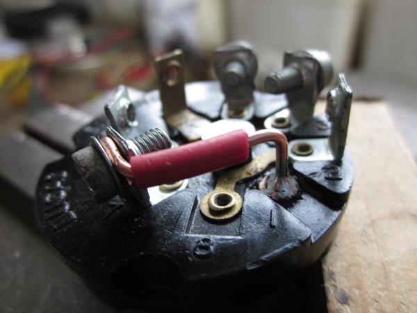
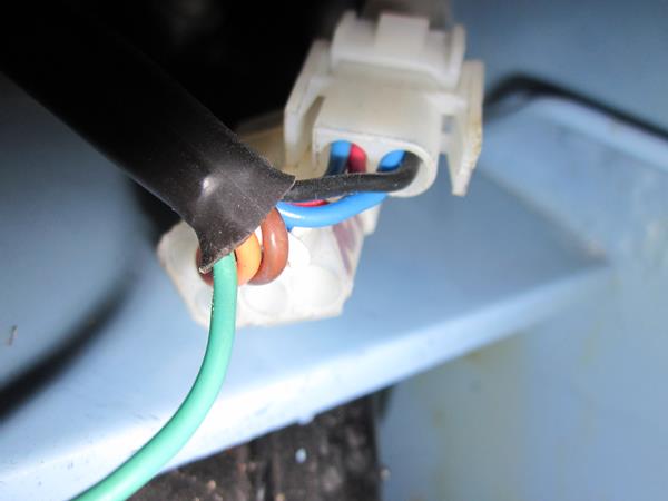
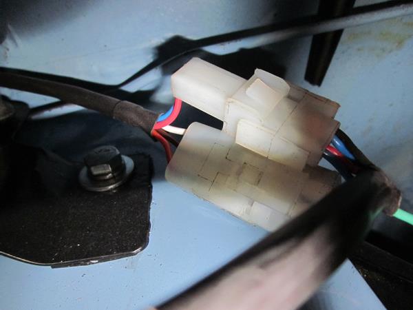
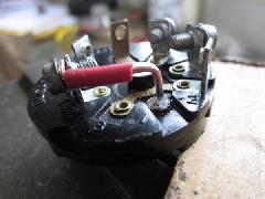
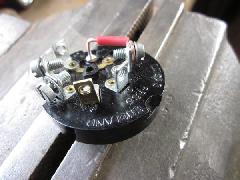
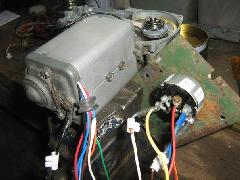
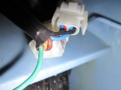
Direction of rotation is fixed during manufacture and will need to be adjusted so that the wipers will park on the pull stroke of the rack requiring different directions of rotation for LHD and RHD cars, and to do this it is necessary to strip the motor and unsolder and switch the connections on the RH and LH terminals shown in the circuit in ET-219D. To avoid this, the Blue and Red wires were taken to the exte-rior of the motor where they can be switched (along with the Black wire to the parking switch) without dismantling the motor.
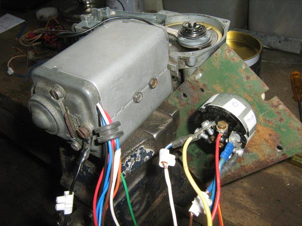
The picture above shows the Red, Blue and Black wires exiting the motor case.
Switching
A relay solution, as developed in ET-219G, is preferred but failing this a PRS5 switch will be used. The relay option requires only short tails on the motor wires but for the switch option the wires have to go back to the dash. However, a PRS5 switch became available and this was used.
Stroke of the Rack
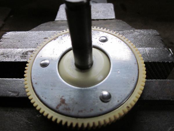
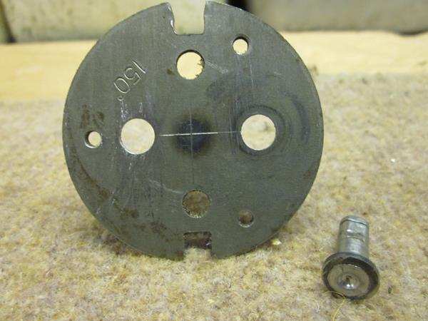
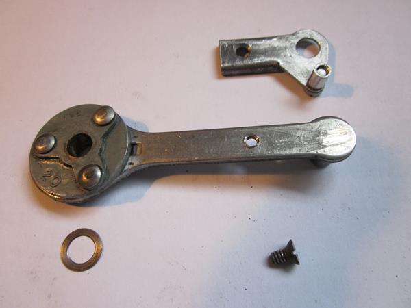
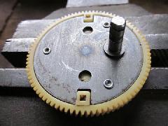
The DR2 gearwheel is stamped 120 degrees and produces a stroke of 25mm. The DR3 gearwheel is stamped 150 degrees and produces a stroke of 31mm so it is necessary to remove the crank pin and relo-cate it 12.5mm from the crankshaft.
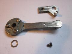
Drill out the peen of the three rivets (0.139dia) and push them out. Dont lose the 0.010 thick thrust washer on the crank pin.
Before removing the crank pin note the orientation of the flats of the double D with respect to the centre lines and replicate it when reassembling the crank pin for welding.
Not having a lathe, I tried grinding on the back side of the crank pin to remove any fillet weld but this did not work so I measured out from the crankshaft to find the centre of the pin and drilled through with an 8mm spot weld drill. The pin came away with a very small spigot which located in a new hole that I drilled with the same drill.
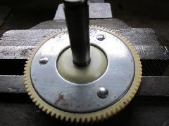
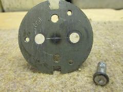
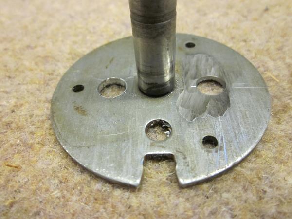
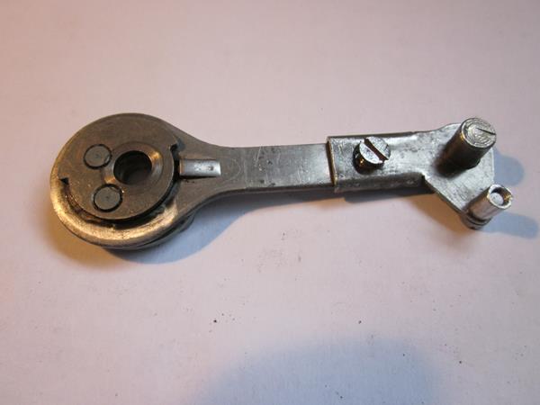
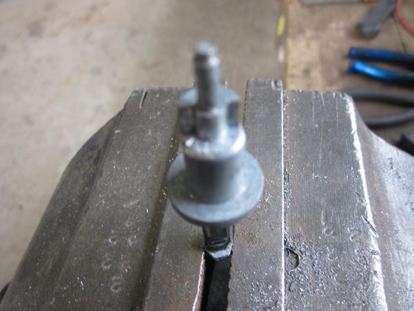
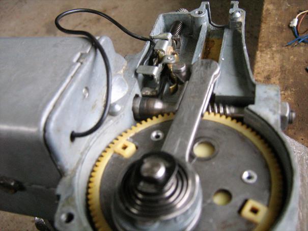
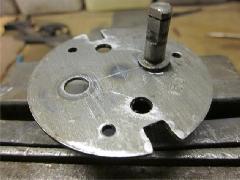
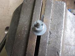
Insert the crank pin in the new hole, with the correct orientation of its flats, and super glue it in position. Then weld and grind smooth. Grinding to remove the crank pin is visible in the first picture below.


There was not sufficient length remaining in the 3 rivets which attached the crank to the nylon gear wheel so 1/8 pop rivets were used. The crank is a tight fit in the wheel and rotational forces are trans-mitted through the dogs on the wheel. The rivets were not popped but cut down and peened over.
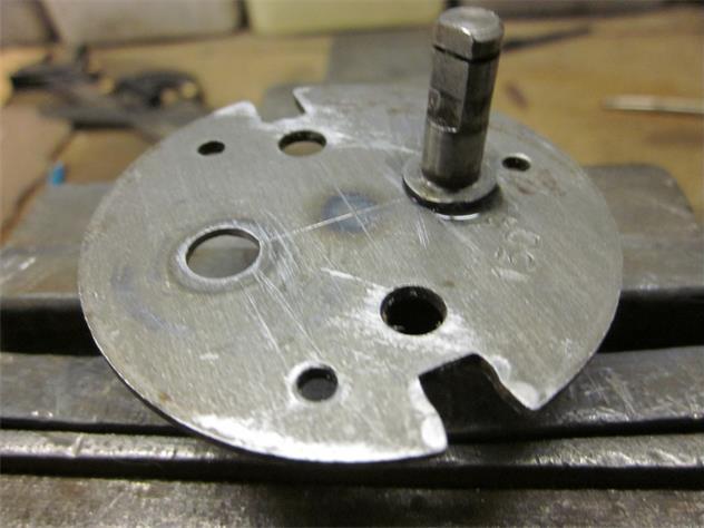
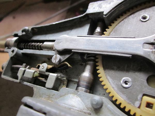
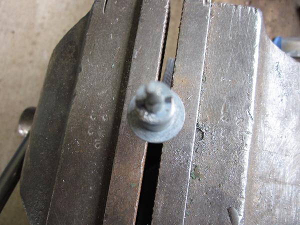
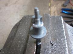
The original DR3 Lucas rack had a trigger attached to trip the park switch but I did not want to commit my rack in case the DR3 did not work for me. Instead I made a trigger to fit over the small end of the con-rod and fixed it with a screw tapped into the body of the rod. The striker is a sleeve tapped for the fixing screw shown in the picture above and below right.
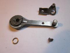
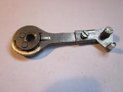

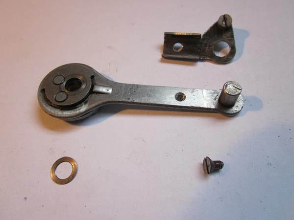
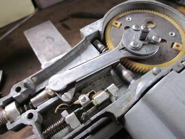
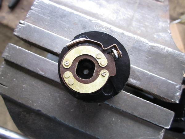
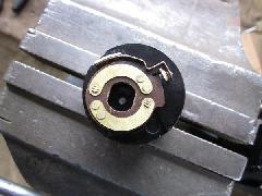
 The last picture shows the retaining mechanism for the crank pin. Fitting over the 3 rivet heads is a kind of swash plate with a double-D piercing, then a conical spring, a washer and a clip.
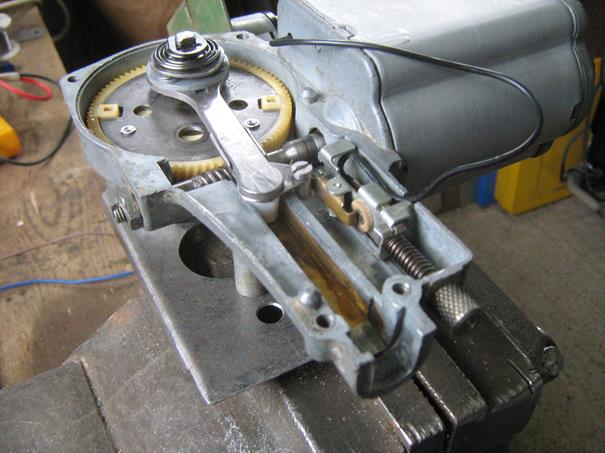
An end float of 0.010 on the worm gear was set on the end float adjuster screw.
The PRS5 Switch
There are two variants of the PRS5 switch. One for 6 wires and one for 5. Unfortunately the switch I bought had only 5 terminals and had to be modified in the armature and in the terminals.
The armature on the PRS5 is a drum with a quadrant removed and this quadrant has to be made into a semicircle. The armature is a light alloy pressed onto a steel spindle. I tried to remove the spindle so that the modification would be a straight filing job, but no way and I did not want to break my precious switch so I had to remove the alloy with a very sharp wood chisel. I set up the armature in a piece of tube gripped vertically in the vice and chipped away to get the shape shown. In fact, the shape is a sector just short of a semicircle, as the centre picture in the bottom row, as this gives more positive switching.
There is no internal connection in the switch to join Terminal 1 to Terminal 7, but there is a hollow rivet at T1. So an external jumper is required to join T1 to T7 as shown.
There is an internal connection for Terminal 5 but no terminal so one has to be made and soldered to the hollow rivet. I made the terminal with a hole to fit over the peen of the rivet so the base of the terminal could be soldered flat onto the washer.
Testing
With the brush connections and the Black park wire brought outside the motor it was possible to test both speeds and both directions of rotation on the bench. The Black wire passes straight through the mo-tor and is left long on the park switch side and adjusted later on.


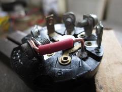
There is a good view of the swash plate washer in the centre picture. The cut-out in the end plate has to be enlarged to accommodate the 3 extra wires. I shrunk a couple of layers of heat shrink sleeve over the wires to substitute for the plastic grommet originally used.
Due to the fiddly connections to the switch terminals I used short jumpers and connectors for the tests.
It is really gratifying to watch the park mechanism reverse and do its stuff, almost a shame to put the cover on.
Mounting
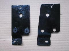
This is the new base plate for the DR3 which picks up on to the original mounts on the heater shelf. It moves the wiper away from LH closing panel and, due to its offset, skews the rack slightly to give a better alignment to the rack tube. I fixed the spacing away from the closing panel first and then did a trial fit with the motor attached at the single upper fixing only and then rotated the motor around that fixing to get the best alignment to the rack tube and marked off the two lower fixing holes on to the base plate.
Installation
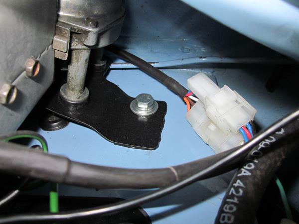
Having got the rotation necessary for a RHD car two harnesses were made, one to contain the motor tails and another to connect to the switch. They were connected with 2 multi-pin plugs with a fuse on the green power supply wire from the existing harness.
The larger plug carries the Orange, Brown and White wires which do not change with change of rotation. The smaller plug takes the Blue, Red and Black tails from the motor harness in the male half where they are joined and continue as Blue and Red into the harness to the switch.

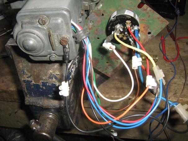
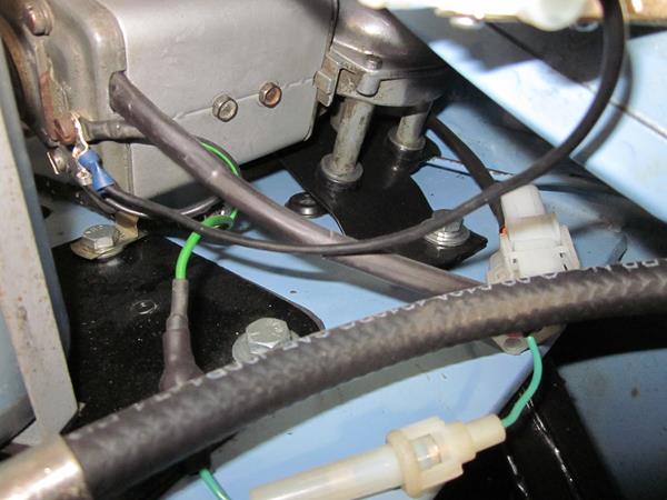
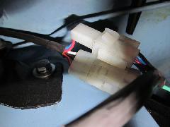 Switchable wires connect in the upper plug with motor tails entering from the right and exiting to the harness to the dash. The lower plug, above right, has Orange, Brown and White wires from the motor and Green power in from the existing harness. The unused Green/Black wire is terminated on the motor earth screw to keep it safely out of the way.
Relay Switching for 2-Speed Wiper
Captain E Blanche from Adelaide, Australia has kindly provided 3 circuit options, Option 1 with relays and a diode, Option 2 with 3 relays and Option 3 with 2 DPDT relays.
Option 1 is not shown. Option 2 will start the wipers at low speed. Option 3 will start the wipers at high speed. The circuits are shown below. If I were using the relay option I would use Option 3.
|