The MGA With An Attitude
WIPER MOTOR REBUILD -- ET-217
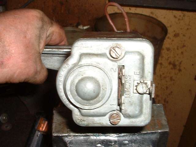
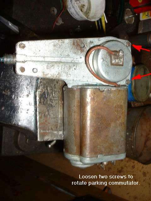
Perquisite to this course is removal of the wiper motor from the car and wiper wheelbox maintenance. With the wiper motor out of the car, take a good look at it
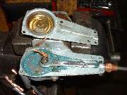
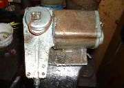 before disassembly. Notice the round cover on the gearbox with a red wire attached (first picture). On older parts with faded color this wire is sometimes interpreted as brown. This cover can be rotated to adjust the park position of the wiper drive. The wire is electrically isolated from the cover for feed through to the inside. It also passes through to the inside of the motor housing to connect to connection terminal 1 on the end plate. For best understanding you may want to keep the motor electrical diagram handy.
Notice also there is an external dimple on the round cover. The cover can be rotated to set the park position of the wiper arms. The arms should park on the left side for LHD car (cable fully extended) or on the right side for RHD car (cable fully retracted). The dimple indicates general direction of the internal crank arm when parked. You may want to make a scratch on the round and flat covers to mark position of the parts before disassembly, so you can set it back to original position with later assembly.

Notice the position of the terminals on the end of the motor. The "E" (earth) terminal is simply screwed to the end plate and does not need to be detached for disassembly. Terminals 1 and 2 pass through the end plate without contact to the case. Remove two long tie through screws to open the end plate.
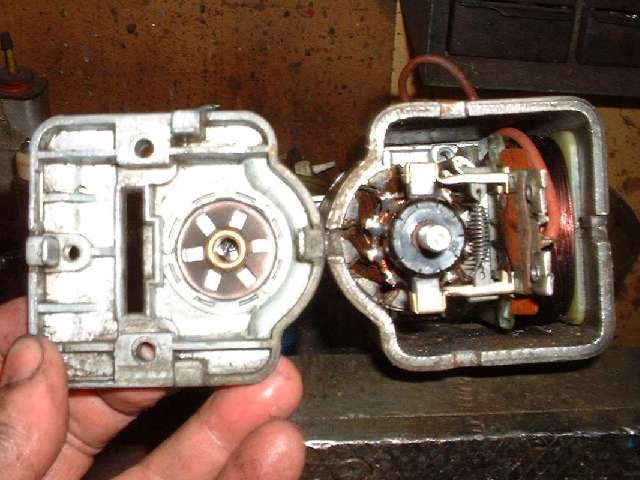
 Inside notice a self aligning bronze bushing in the end cover, and a thin metal thrust washer on the motor shaft (don't lose the little bits). Such bronze bushings and electric motor brushes might be found at a good local hardware store. This particular motor has been in use in my MGA for 37 years and 345,000 miles (as of this writing) in all types of weather, lots of rain and sometimes snow. This is only the second time the motor has been opened, and the bushings and brushes are still in excellent condition. If all goes well it seems to be happy with a good cleaning and re-lube every 15 or 20 years. If the vehicle is left to set for many years the wiper drive is likely to have more problems with dried out grease, slow operation, seized bearings, or dirty commutator (bad contact for the brushes).
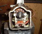
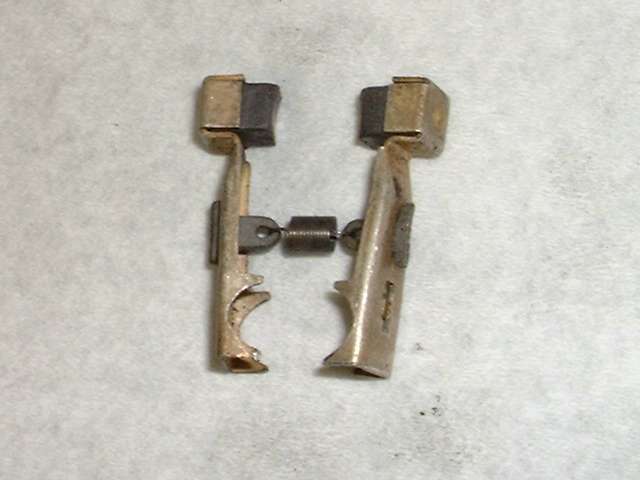
Here a close look inside reveals the brushes mounted on pivot arms and being pulled together with a tension spring to make contact with the commutator. The spring is electrically isolated from the arms by fiber end links. The arms are electrically connected to terminals 1 and 2 at the heal pivot point of the arms. This makes the armature electrically connected in parallel with the field coil so they both see full system voltage when running.
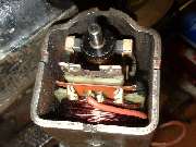
Tilting up a bit we can see the field coil below the armature, the heal pivot ends of the brush arms, and the wire connections to terminals 1 (on left) and 2 (on right). Notice also the thick red wire connected to terminal 1. This is the same wire noted earlier as connected to the round cover on the gearbox. Notice also the orange fiber insulator, which will come up later.
Now you can gently tap the motor housing loose from the gearbox, and lift off the motor housing (including the brushes) while leaving the armature in place. To do this you need to pull the red wire through the gearbox end plate. Note how the wire runs along the side of the coil. To allow sufficient length you can rotate the round cover a bit. Or you may remove the flat cover from the gearbox and tilt it to allow the face of the round cover to approach the gearbox end plate. This is a good time to replace the red wire if it is damaged. Use the old wire for size and length reference. If the wire should short to ground on the motor housing the motor would run continuously.
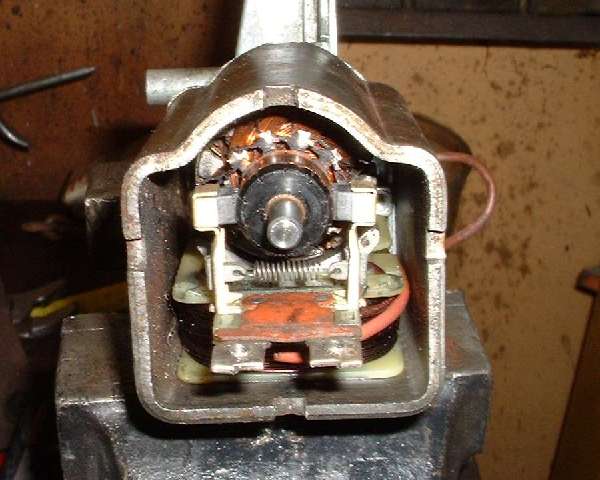
 Looking through the motor housing You can see the field coil and the brush arms still in place (at the far end). With the field coil powered by direct current, the curved cradle end will be north magnetic pole while the motor housing will be south magnetic pole. Change of vehicle electrical system polarity will exchange the magnetic poles, but no matter, as the armature is connected in parallel with the field coil and will also change polarity accordingly. As such the change of vehicle electrical system polarity does not affect motor rotational direction, and no change of wiring on the wiper motor is required.
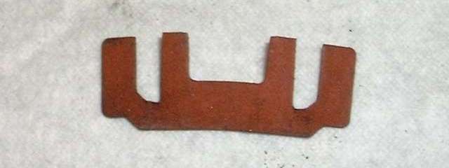
 Back at the tail end of the motor housing you can extract the orange fiber insulator mentioned earlier. This allows withdrawal of the brush arms along with the connecting spring. If the carbon brushes should happen to be worn down close to the metal carrier box, the brushes should be replaced.
Suitable replacements may be found at any electric motor shop, and commonly at a good local hardware store. The only critical feature is the rectangular cross section size of the brush. If it comes with a wire attached the wire may be cut off. If the new brush is too long it may be ground to the correct length.
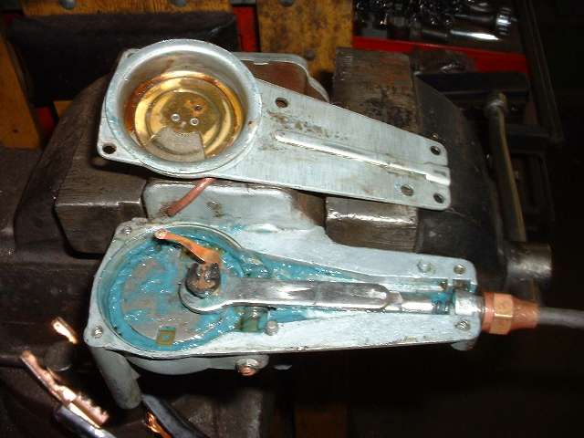
 To open the gearbox remove four hex head screws and lift off the cover. (This picture is out of sequence, showing clean grease after it was cleaned and reassembled). The crank link and parking commutator contact are secured to the crank gear by a circlip in top. Removing the circlip allows you to lift off the copper contact finger and the crank link. Then lift our the slider and the cable bushing. You should also find a thin thrust washer on the crank pin below the crank link (connecting rod).
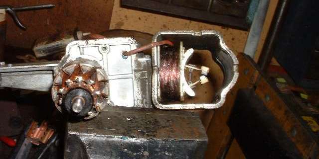
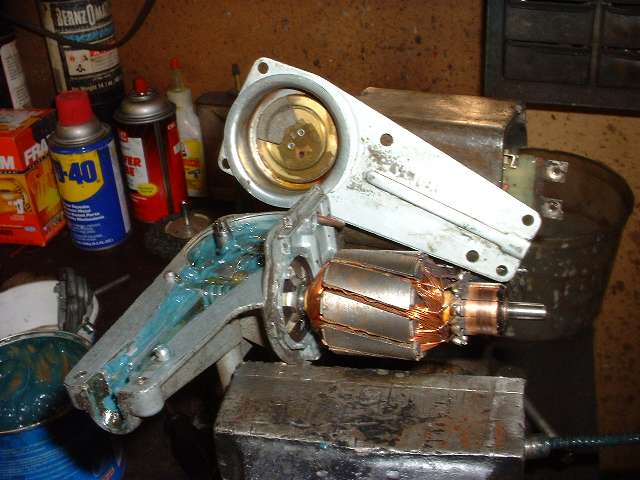
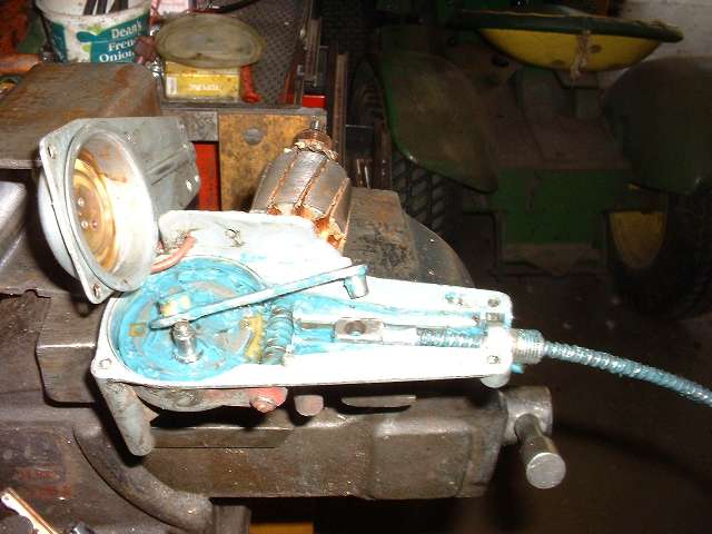
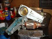
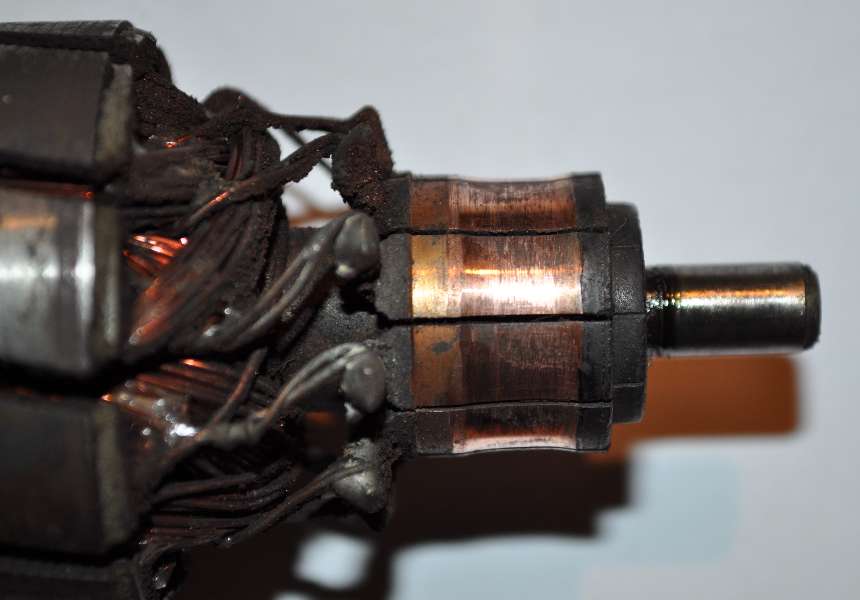
Here we have a view of the open gearbox and armature with the gearbox cover and motor housing behind. The crank arm, slider and cable have been removed. Where the armature shaft (with worm gear) passes into the gearbox you can see the second bronze bushing and a retainer clip. On the commutator you may note some light carbon deposits, which is perfectly normal. The copper commutator can be cleaned with a rubber pencil eraser.
|
|
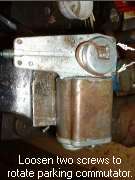

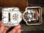
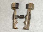
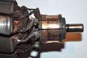
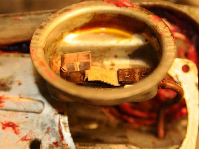
Here is a different style parking commutator that you may find in these units. This has a spring loaded contact arm inside the round cover. Each time the crank pin comes around it deflects the spring arm to break the grounding contact to provide the parking function. Externally it looks and works much the same, just rotate the round cover to set the park position. (Thanks to Cliff Jones in South Carolina for these pictures.)
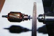
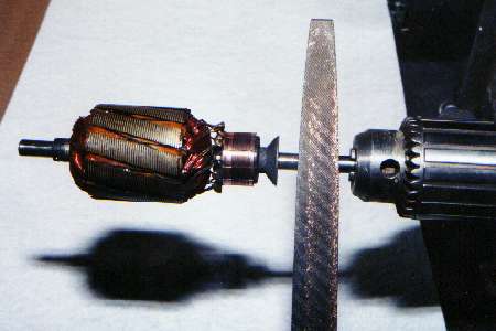
 If perchance the commutator should be scratched or grooved it can be cleaned up. Chuck the armature in an electric drill, being careful not to mar the bearing surface on the shaft. Hold the drill securely, preferably attached to a work bench or held in a vice. As the armature is turned slowly with drill power you can use a fine tooth flat file to dress the cylindrical surface of the commutator. (second photo is a heater motor armature). Remove only enough material to achieve a smooth surface. Clean off all copper dust before reassembly, paying particular attention to removing any copper particles which may be lodged in the grooves between the segments of the commutator.
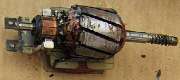 The field coil is held in the housing with a pair of self tapping screws which might be fairly tight or possibly even corroded in place. Be careful not to break the screws if you want to remove this part. Here we have a picture of the field coil removed and reunited with the armature and brushes.
On 3/21/2008, James Clark wrote:
"The lacquer was flaking off of the field windings of the motor, I sprayed clear coat on the field windings to keep the moisture at bay."
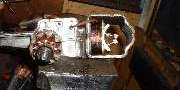
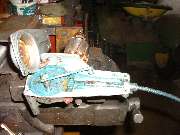 Here we have a view of the gearbox being reassembled with the crank arm lifted out of place. Lift out the crank gear and slider parts, clean everything and re-lube with grease prior to reassembly. Notice on the near side of the gearbox, directly in line with the end of the worm gear shaft, there is a set screw with a locking nut. This is used to adjust end float of the armature shaft after the motor case has been reassembled to the gearbox. It will most likely not need any adjustment, having very little wear, as thrust on the shaft is in the opposite direction when running. If the armature seems to have excessive end float, investigate to be sure you didn't leave out a thrust washer.
This picture has the guts of the gearbox reassembled including the output drive cable and connecting tubing. The crank arm is in place between the crank pin and the slider. On the top end of the crank pin is mounted a spring copper arm which makes electrical contact with the parking commutator in the round cover. The crank gear turns clockwise so the contact drags around the commutator. Order of assembly is gear wheel with crank pin, thin thrust washer on the crank pin, crank link, copper spring contact arm and circlip.
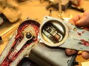
Notice the copper disc inside of the round cover with a large pie slice gap and fiber insulator behind. It is this gap in the disk which breaks the ground connection with the copper contact to cause the motor to stop running for the park position. This is where you can control the park position by rotating the round cover. Also notice the dimple on the outside of the round cover (picture below). The dimple indicates the park position of crank pin. For LHD the cable needs to be fully extended to park the wiper arms on the left, so the dimple points toward the cable tube. For RHD the cable needs to be fully retracted to park the wiper arms on the right, so the dimple points away the cable tube. If you should choose to relocate the wiper motor to the opposite side of the car for convenience of servicing, the park position of the cable will be opposite.
Per common tradition, reassembly is the opposite of disassembly. Maybe clean the grease off before you put it back in the car. When it's back together you can test it by applying power + and - to terminals 2 and E respectively for negative earth, or + and - to E and 2 respectively for positive earth. Connect terminal 1 to E to make it run. Disconnect terminal 1 to allow it to park. Rotate round cover to set the park position. Park position will be slightly different running free vs under load, so this may require a small re-adjustment after installation.
As a side note, the steel body of the wiper motor was not originally painted for the MGA. For concours originality you can buff the rust off of the motor case and spray it with clear lacquer. If originality is not an issue, a coat of black enamel might be nice. The gear case and motor end plate are cast alloy. The flat and round covers are stamped steel and originally galvanized (Zinc plated).
 Addendum January 2010:
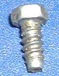
Since someone asked, I pulled a screw our of the gearbox cover on my wiper motor for photo and measurement. It is a #8-18x3/8 Type-B thread forming screw with 1/4" hex head, zinc plated steel. Notice the pilot diameter on the nose and the lead-in thread.
McMaster-Carr has a reasonable replacement part, not the same head style. #8-18x3/8 Hex washer head slotted zinc plated, 93880A192 - $8.65/100.
 Go to www.mcmaster.com. Put 93880A192 in the Search/Find box. When the highlight box comes up on the catalog page you get a full description of the part. You can also click to get a CAD drawing.
|

 If perchance the commutator should be scratched or grooved it can be cleaned up. Chuck the armature in an electric drill, being careful not to mar the bearing surface on the shaft. Hold the drill securely, preferably attached to a work bench or held in a vice. As the armature is turned slowly with drill power you can use a fine tooth flat file to dress the cylindrical surface of the commutator. (second photo is a heater motor armature). Remove only enough material to achieve a smooth surface. Clean off all copper dust before reassembly, paying particular attention to removing any copper particles which may be lodged in the grooves between the segments of the commutator.
 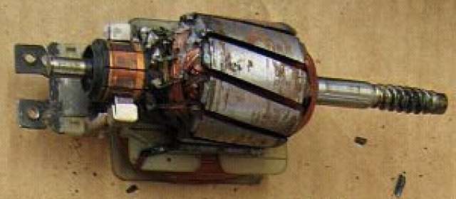 The field coil is held in the housing with a pair of self tapping screws which might be fairly tight or possibly even corroded in place. Be careful not to break the screws if you want to remove this part. Here we have a picture of the field coil removed and reunited with the armature and brushes.
  Per common tradition, reassembly is the opposite of disassembly. Maybe clean the grease off before you put it back in the car. When it's back together you can test it by applying power + and - to terminals 2 and E respectively for negative earth, or + and - to E and 2 respectively for positive earth. Connect terminal 1 to E to make it run. Disconnect terminal 1 to allow it to park. Rotate round cover to set the park position. Park position will be slightly different running free vs under load, so this may require a small re-adjustment after installation.