The MGA With An Attitude
VOLTAGE CONVERTER - ET-207
Installing a NEGATIVE EARTH RADIO
in a POSITIVE EARTH CAR (or vice versa)
This is one of those Gee Whiz tricks that can impress people if you get it right (which is actually pretty easy), or can burn your car down to the ground if you get it wrong (which is also pretty easy). I should say right up front that it is generally easier to convert the car's electrical system to negative earth, which would allow you to then install any number of electronic gadgets.
The only people who should even think about installing a negative earth device in a positive earth vehicle should be devout members of the Positive Earth Society who insist on keeping the car's electrical system wired as positive earth for concours reasons, while installing some negative earth electronic device(s), which wouldn't be concours anyway. Anyone else should just convert the car to negative earth. Still, I have bumped into a few people who insist on doing this, so here goes.
Let me first describe the WRONG way to do it, which many people brashly assume is the only way. You could build an electrically insulated isolation cabinet around your new negative earth radio, and mount it in the dash while being careful to keep it electrically insulated from the dash panel. Then just swap the power input wires, connecting the vehicle hot wire to the radio chassis ground, and connecting the vehicle ground wire to the power terminal on the radio. This could work (maybe), but it also raises some other possible shorting and grounding problems.
If there might be any exposed metal part(s) on the front of the radio, just touching your car keys or a ring on your finger between that metal point and any other electrically conductive grounding point on the car could cause a power short. If you're lucky (and well wired) it might blow a fuse. Not so lucky, it might burn your fingers, destroy some radio circuits, burn up some wiring, or worse. And it is hard to be sure that there is nothing conductive on the front of the radio. There could be something as seemingly innocuous as a steel set screw holding a dial knob on the shaft, or a steel nut trying to hide behind the dial knob and holding the radio in the face plate. Drop a key or a coin in there, and you might be swearing quicker than you think.
Another possible problem could be if the antenna is electrically grounded on the body of the car. The antenna signal lead is commonly a coaxial cable with the outer braided jacket used as a grounded electrical shield to protect the central signal wire from extraneous electrical interference, like ignition spark noise. That outer jacket is commonly connected to the chassis of the radio. If it also happens to be connected to the antenna body mounting bracket at the other end, you're stuffed. Then you start thinking about how to electrically isolate the antenna mount from the car body. And then you may want to think about what happens if you accidentally short the antenna mast to the chassis of the car.
Enough of that stuff. Let's get on with the RIGHT way to do it. The right way is to install the radio in a more normal fashion with the cabinet nicely grounded on the dash (if you like) and/or grounded to the chassis of the car. Then also install a voltage converter device (which is commonly referred to as a voltage inverter). This device appears to electrically use the battery -12 volt output to create a +12 volt power input for the radio. The hookup schematic is commonly drawn something like this:
The little trick here is to keep the ground potential of the radio chassis at the same voltage level as the ground potential of the car chassis. We commonly think of this as zero volts at body ground. So you will never get a spark or a blown fuse or an electrical shock or any wiring fire by shorting the radio housing to the car body. In fact the radio housing (and the antenna) might be always shorted to the car body, and it works nicely.
Notice that the "voltage inverter" has two ground connections. This is because the device should have 12V input and 12V output, and the input and output should be eletrically isolated internally. You might also notice that the diagrams do not have polarity symbols on the converter gound connections. This is because they are floating ground connections, and they will assume whatever voltage is on the car chassis (both of the unlabeled terminals having the same voltage).
But there is another way to look at this electrical schematic. It's all relative. When measuring voltages with a volt meter, you can use any point in the electrical system as the zero volt reference point, and you can measure the voltage relative to that at any other point in the electrical system. For the sake of this new view, let's use the negative post of the battery as the zero volt reference, and measure everything else relative to that, which will make all of the readings 12 volts higher. Poking around the same circuit with a volt meter would give you these voltage readings:
This gives an entirely different impression of what the voltage converter is doing. It is in fact taking the 12 volt supply from the battery and doubling the voltage to create a 24 volt output which is used to power the radio. The radio then sees a +24 volt input and a +12 volt ground reference, which gives it a net 12 volt power supply with the desired polarity. So the power converter box is in fact a voltage doubler, which only looks like a polarity changer. If you physically attach the voltage converter to the radio, or logically treat it as part of the radio, then your negative earth radio magically becomes a positive earth radio for use in your positive earth car. Cute, huh? Another casual observation is that the converter 12V input and 12V output appear to be connected in series to make 24V.
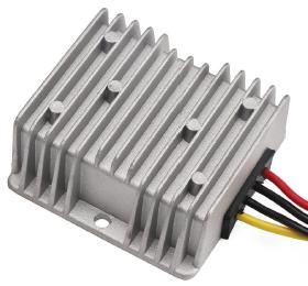
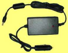 The nice part is that as long as you don't need too much power for the radio, the voltage converter could be really cheap and small (and easy to hide). I have seen a small converter (maybe 10 watts) selling on eBay occasionally for as little as $10 (opening bid price). The full retail price of a new 50 watt converter should be under $60 (maybe less if you shop around). I just Googled up a 60 watt unit on the net for an MSRP of $85 (picture at right). The body size is about 1"x2"x4" (about the size of a charger for a laptop computer). This is a Power Stream model ED1060-24 (I hope the link stays good for a while). It is 88% efficient, so at the maximum 60 watt output it may draw 68 watts of power and generate 8 watts of heat.
Addendum May 2005:
At 06:14 PM 5/4/05 -0600, Brent Kasl wrote:
"I have an original Alpine with positive ground. The only reason I have not switched to negative ground and add the alternator is to keep my original positive ground radio in the car. It does not have a switch on the back from pos-neg. Is their a way to change the radio to neg w/o damage???"
Probably not. However, if you want Negative ground, and you want to keep your positive ground radio, you can use a voltage converter. Most people do this to run a negative earth radio in a positive earth car, but it works just as well the other way around. Just swap all the + and - signs on the diagram, and you have it.

Addendum September 2005:
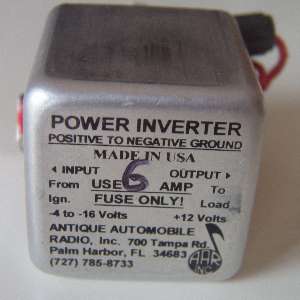
Here's a slightly smaller "Positive-to-Negative Ground High-current Converter" for $70 from: Antique Automobile, 700 Tampa Rd., Palm Harbor, FL. phone 800-933-4926. It is a 1-3/4 inch cube. It wants a 6 amp fuse, so I suppose it's good for 50 watts output.
 Addendum February 2013:
On 2/21/2013 -0700, John Moglia in Phoenix, Arizona, USA wrote:
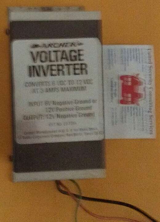
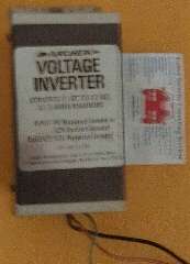
"I installed an Archer (Radio Shack) inverter which converts either 6 or 12 volt positive earth to 12 volt negative earth. It is part number 22-129A. Unfortunately the device has been out of production for years but used ones do surface from time to time".
Parked beside a business card, this inverter appears to be about 3-1/2 x 5-1/4". Old technology is not particularly small.
Addendum, December 2016:
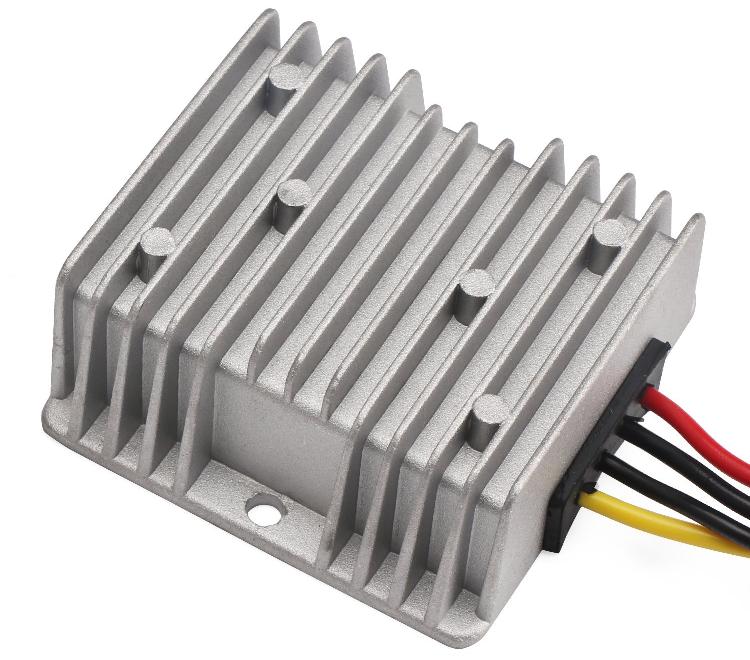
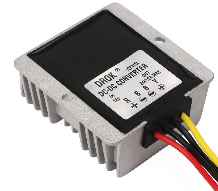
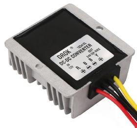
Here is a DROK 122412L converter good for 12-amps, 288 watts output.
Found on Amazon (for as long as the link might last).
Also found on eBay as Fulree 122412 (for as long as the link might last).
On 1/19/2018, Jonathan Colley wrote:
"The two -ve leads of the converter are connected, so the diagram should show minus on the output of the converter connected to minus on the input of the converter. In my application I merely left the output black wire unconnected (it's not needed). The yellow output wire then is at +12v relative to the vehicle chassis".
So, this DROK power converter is NOT an an internally isolated inverter, because the two black wires are internally connected together, intended to be a common ground. It is in fact a +12V to +24V power converter with internal connection between input and output. It can still be used for the purpose intended here, to connect a 12V negative earth radio to a 12V positive earth car, but the wiring needs to be a bit different.
The diagram above shows the +12V to +24V converter connected to positive earth chassis and negative earth radio. The trick is same as above with radio input power connected between +24V and +12V to have net 12 volt positive supply for the radio while the radio is still grounded to the car body or chassis. Notice that only one of the black wires on the converter is connected externally, and that it is a hot wire, not grounded. The other "-" terminal of the converter is connected internally and need not be connected externally (unless you want to connect it to the other converter "-" terminal or to the battery hot terminal). Do NOT connect radio "-" to either "-" terminal on the power converter (although it wouldn't hurt if you connected radio "-" to converter red wire, as they are both grounded).
The diagram above assumes your volt meter black wire (-) is connected to battery "-", which emphasizes the 24 volt output of the converter. The diagram below is identical, but assumes you have the volt meter back wire connected to battery "+". This makes the DROK voltage converter look more like the desired voltage inverter. As noted, it is just a matter of perspective. This same scheme may be applied to any +12V to +24 volt converter that is NOT internally isolated.
It should be noted that the DROK voltage converter cannot be used to connect a 12V positive earth radio to a 12V negative earth chassis. I will leave it to the reader to try to diagram it. The radio requires the ground connection to be 12V difference from the power input. With converter output at +24V, the second radio connection would have to be either +36V or +12V. There is no 36V source anywhere in this circuit. The radio could be connected between converter +24V and battery +12V, and the radio would work. But that gets back to the radio ground connection being different voltage potential than chassis ground reference, so you would have to electrically isolate the radio from the car body, which is exactly what we were trying to avoid by using the voltage inverter.
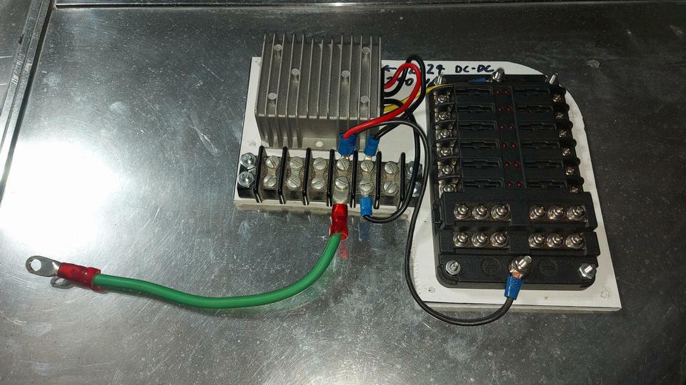
On 12/3/2023, Montgomery Gisborne wrote:
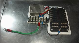 I also constructed the ET207 (voltage converter) as per your website and found it to function exactly as described! Extremely ingenious hack, I would never have figured that one out on my own. I constructed it as a panel for easy installation as a unit under the dash. I should have taken a picture of the look of astonishment when I connected the device and voila! Instant 12-volt negative-ground power".
|