The MGA With An Attitude
Installing an ELECTRIC TACHOMETER in the MGA - ET-202C
When people install a 1965 or later MGB 1800 engine in the MGA (fairly common actually) they lose the mechanical tachometer drive. The common fix is to install the Smiths electric tach from a 1965-1967 MGB. This unit is originally positive earth and will work as is in the MGA with original positive earth wiring. If the electrical system is switched to negative earth this tachometer must be converted to negative earth.
( Click for larger pictures. )
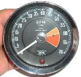
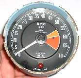
 Here are pictures and notes for the electric tach conversion for MGA. The first photo shows the face plate with logo reading:
RPM X 100, 4 CYL, POSITIVE EARTH
RV12401/00B, SMITHS, MADE IN U.K.
IGNITION
Note that the word "IGNITION" is partially obscured by the glare shroud. Model numbers RV12401/00A and RV12401/00B are functionally interchangeable, but when you open the case you may find some variation of parts inside.
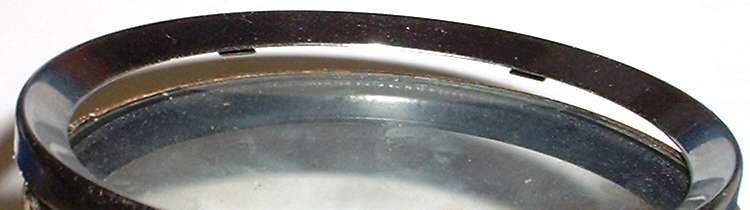
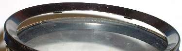 Twist the front chrome ring to align the tabs with slots for removal. Also remove the glass and glare shroud, which will have an O-ring seal in between. You can insert a sharp knife blade behind the edge of the glare shroud to pry it forward from the case. Do not attempt to pry the edge of the glass from the glare shroud (as you might chip the glass), but remove this as an assembly. A rubber O-ring between the glass and the glare shroud is likely to be securely stuck to both parts. You may not need to separate these parts unless you are very particular about cleaning the back side of the glass.
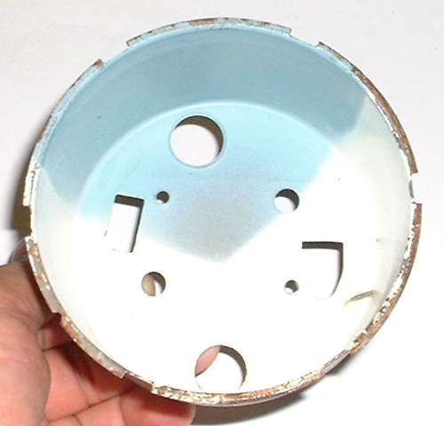
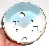 On the left we have the instrument with the glass and glare shroud removed. On the right you see the empty case. Notice the white interior of the case with some light blue color in the upper part for about 120 degrees surrounding the position of the illumination lamp. This blue area serves to dim the illumination a bit near the bulb to even out the lighting somewhat around the face. It also gives the illumination a slight blue tint.
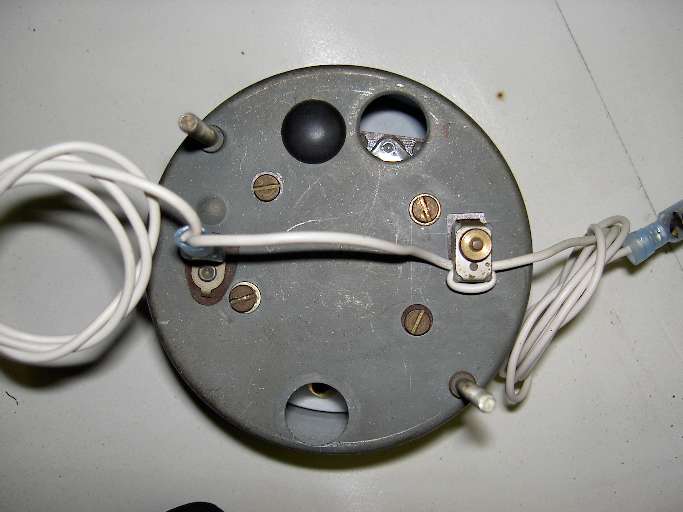
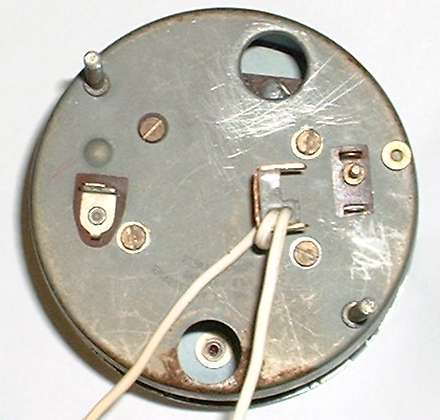
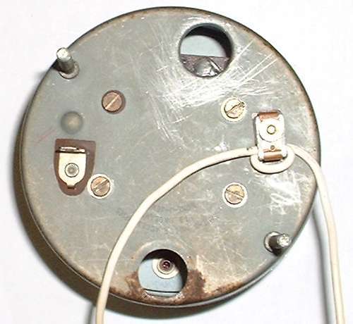
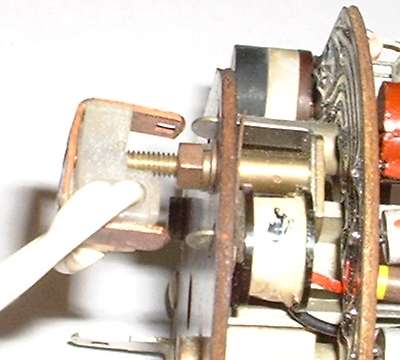
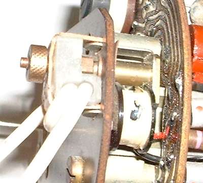
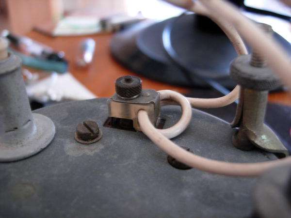
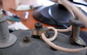
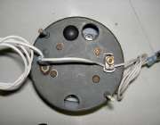
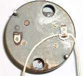 The picture at near right shows the back of the instrument with power terminal on the left and induction loop on the right. The white wire is part of the wiring harness running from the ignition switch to the ignition coil. To remove the instrument from the car without cutting the wire, remove the knurled nut, unplug the copper strap, and leave the nylon insulator on the wire (second picture).
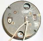
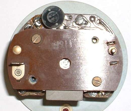
 For disassembly remove front glass as noted above and the induction loop bracket. Then remove the two screws on the back of the unit that hold the internals to the case (not the two whose heads fit in holes in the case), and allow the internals to drop carefully into your hand. Do not bend the needle! Once the case is removed the back of the internals looks like the picture at left. Notice the black knob at top just left of center with two white dots and a screwdriver slot in the center. This knob may be a different color (commonly white) in your instrument. This is the potentiometer used to calibrate the instrument for correct speed reading. [See photos and notes at bottom of page for external location of the calibration knob].
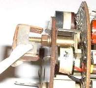
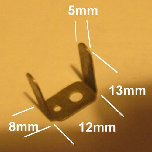
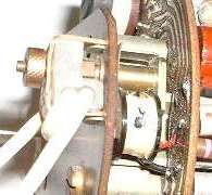 Here we have internal pictures of the induction loop connector on the back of the instrument. When this is assembled it has to make electrical connection at the ends of the copper strap. This coupling works similar to a transformer. As the contact points in the distributor interrupt the flow of current to the ignition coil, the current surge in the white wire induces an eddy current in the copper strap which circulates in a loop through and around the small coil inside. That coil picks up the small inductive signal to feed the tachometer drive circuit.
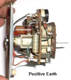
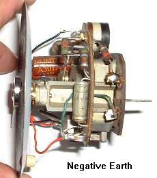
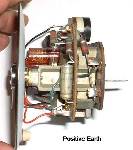
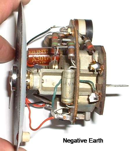
Here we have before and after pictures of the internal modification to convert the tachometer from positive earth to negative earth. Different variations of this instrument may have different resistor values, so the stripes on the resistors may be different color. The spade terminal on the back is the power input, and the terminal next to it is ground (earth connection).
NOTICE: If when you open your electric tach you find that it does not have this green wire connection, then you have a more rare variation of the instrument which requires different technique for conversion to negative earth. For that operation see ET-202B.
Un-solder the connections for the green wire and the large resistor on the rear circuit board tabs. Switch the ends and re-solder the connections. For original positive earth setup the resistor connects to negative power and the green wire connects to positive ground. For negative earth conversion the green wire connects to positive power and the resistor connects to negative ground. Internally the instrument then has the same electrical polarity with the green wire always being positive. Clean the glass and reassemble the instrument when finished.
 When converting to negative earth you will also need to reverse the direction of the induction loop on the back of the instrument (because current flows the opposite direction through this wire). The white wire comes from the ignition switch, goes through the induction loop, and continues on to the hot side of the of the ignition coil. In the MGB this wire (including the nylon insulator block) is part of the wiring harness. Referring to the illustration above, select one of the wires and tag it with two pieces of tape for identification. Then, cut the wire between the pieces of tape, and cut the other wire to the same length. Reverse the connection (now there is one piece of tape on each wire) and solder them (remember, this is the power lead for the coil and is un-fused). Tape the connections carefully. When later replacing the plastic block on the back of the tach, ensure that the metal band around the block is carefully positioned. This is a necessary part of the electromagnetic pickup.
Alternately, if you were a little crafty you could cut the wire on one side only. Then pull the wire out of the insulator block and thread it back through from the other side with the wire loop circulating in the opposite direction. Finish by soldering and taping the wire back together. If you cut it on the left you solder it on the right after re-routing, or vice versa.
The MGA originally has the cable driven mechanical tach. Here a single white wire from the ignition switch runs to the fuse block for input to one of the fuses. From there the white circuit branches to feed the ignition coil and the fuel pump (both un-fused). When installing the electric tach in the MGA the white wire for the tach running between the ignition switch and the ignition coil has to be separate from the white circuit powering other things in the car. For this you need to disconnect the white wire feeding the coil from the fuse block. Connect this wire to a new length of white wire which will run to the tachometer. The white wire return run from the tach can go directly to the ignition switch (shorter run), or it can run back to the original connection on the fuse block to pick up power from the switch.
In any case the trick here is to finish with the white wire loop on the back of the tach turning in the right direction to make the tach work. Purely at random you have a 50/50 chance of getting it right (or wrong) on the first try, and if it doesn't work you have to reverse the direction of the loop. That's as close as I can come to telling you which way the loop should run. I had a chat with John Twist, and he said the same thing, flip a coin, and don't make the final hookup of the induction loop until you know it works.
Not to forget, the electric tach also needs power and ground connections The original black wire in the MGA harness which provides ground for the instrument illumination lamp will also provide the earth connection for the tach. The power feed for the tach can be another wire from the ignition switch or from the fuse box. An easier method may be to run only one white wire from the ignition switch to the tachometer power terminal, then start the induction loop from there.
If your electric tach is not indicating the right speed it will need to be calibrated. When you reverse the electrical polarity of the tach it will almost certainly have to be recalibrated. Report is that turning the calibration knob clockwise will reduce the indicated speed output, anti-clockwise increases it. If turning the pot does not give a good consistent output right away, the contacts inside the pot may be dirty. Try turning the pot back an forth a few times all the way to both ends of the adjustment (about 270 degrees rotation) to clean the contacts. If you cannot get the instrument to operate, or you cannot get it to respond with the expected speed indication, give in and send it to Nisonger Automotive. They know how to fix it to make it work.
There are a few methods for finding a speed reference for calibration.
a.) Use a known good tachometer or a good garage test tach for speed reference.
b.) Compare the tachometer to the speedometer and set accordingly. You can check the speedometer accuracy by driving on a road with distance markers, using a clock, and calculating the speed vs. time. You can calculate engine speed knowing tire diameter (rolling radius or turns per mile) and final drive ratio.
You need 12 volts power and ground to make the tach work. For positive earth tach connect +12 volts to the tach case ground, and -12 volts to the power input terminal. For negative earth tach connect -12 volts to the tach case ground, and +12 volts to the power input terminal.
The battery charger will only supply the pulsing signal for the induction loop. How you connect the battery charger terminals for calibration depends on direction of the induction loop. If you get it wrong it should cause no damage just won't work. In that case reverse the charger connections on the induction loop, and it should work.
The induction loop normally carries 3 to 4 amps for power to the ignition coil. If you think your battery charger might supply more than 4 amps, then connect a 3-ohm 50-watt power resistor in series with the induction loop to limit current to 4-amps at 12 volts.
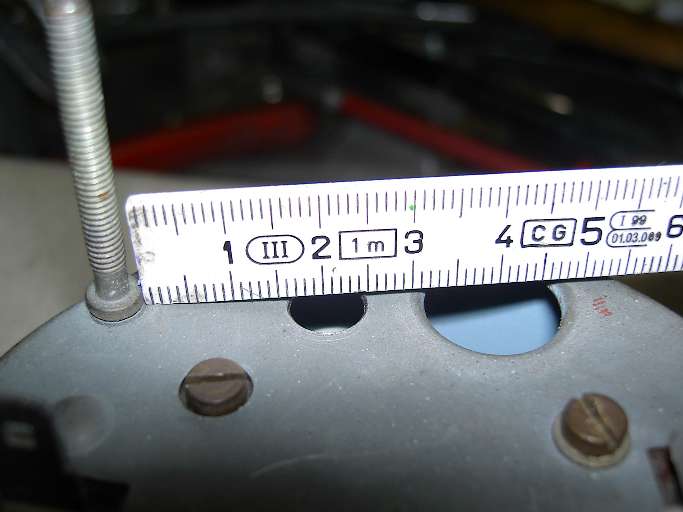
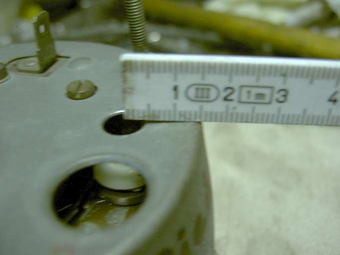
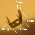
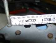
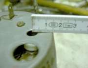
Having disassembled the electric tachometer once for polarity change or calibration, you may not want to do it again. You can provide a hole in the back of the case for access to the calibration knob if it should ever be needed again. Pictures below show location for that hole.
2.0-cm (0.79-in) from the mounting stud base diameter.
1.5-cm (0.59-in) from edge of the case.
Install a snap plug when finished.
On 3/16/2015, Frank Bruns in Austin, Texas, USA wrote:
First, retain the light and socket for ignition warning light for the MGB tach. The MGA socket wont fit the back of the MGB tach. Same goes for the mounting bracket for the MGB tach. The MGB tach case is 0.10 'longer' than the MGA case and it makes a difference.
Second, the MGB tach (positive or negative ground) works well with a stock points and condenser ignition, but fails with most electronic (Pertronics, Crane, etc). This is not an MGA problem. The MGB forums are full of threads concerning tach failures after converting to electronic ignitions. Nisonger has a (full internals swap) fix, but it isnt cheap. I dont know if a second loop on the input 'transformer' would increase the input voltage enough, but it might be fun to experiment.
Addendum December 6, 2018:
 Above: Tachometer circuit in 1965-1967 MGB Above: Tachometer circuit in 1965-1967 MGB
Below: Circuit to install this tachometer in the MGA
These are current sensng tach with inductive loop, Positive Earth.
 Be sure there will be a black ground wire from the harness connected to the instrument mounting bracket (as original). And you will need the appropriate bulb holder for the ignition lamp in the MGB tach (different from the MGA ignition lamp bulb holder).
For negative earth conversion, swap the two primary terminals on the ignition coil, and modify the tachometer for negative earth operation.
|
 Having disassembled the electric tachometer once for polarity change or calibration, you may not want to do it again. You can provide a hole in the back of the case for access to the calibration knob if it should ever be needed again. Pictures below show location for that hole.
2.0-cm (0.79-in) from the mounting stud base diameter.
1.5-cm (0.59-in) from edge of the case.
Install a snap plug when finished.
Having disassembled the electric tachometer once for polarity change or calibration, you may not want to do it again. You can provide a hole in the back of the case for access to the calibration knob if it should ever be needed again. Pictures below show location for that hole.
2.0-cm (0.79-in) from the mounting stud base diameter.
1.5-cm (0.59-in) from edge of the case.
Install a snap plug when finished.