The MGA With An Attitude
ADDING FUSES, how many and where to put them. - ET-201B
So I haven't been able to talk you out of adding more fuses? And you're thinking you might like to have several additional fuses, and maybe some relays too? I have put some thought into how may fuses might actually be useful in the MGA (other than zero), and how and where to install them for ease of servicing, least modification of the original wiring harness, and least visible intrusion on the original car design.
Consider first that there are four green wires connected to one fuse in the original MGA setup. Refer to the switched fuse wiring diagram. Also consider there are many devices that were not originally fused. Refer to spark and fuel on white wires and to lighting circuits on blue wires or red wires.
You might replace the original two-fuse holder with a larger multi-fuse holder with as many as 6 fuses (maybe including a spare for some unspecified accessory). In this location two green wires go to brake light switch and turn signals. For the MGA 1500 the brake lights are the same bulbs as the rear turn signals, so they should remain combined on a single fuse to avoid parallel fusing anything. For the MGA 1600 the brakes lights have separate bulbs and are on a different circuit from the turn signals, so these could be put on separate fuses. A third green wire runs to the wiper motor, which could certainly be fused by itself. And don't forget the original always live fuse for the horn. So far we've specified 3 or 4 fuses in the original location.
Where the white wires connect to the A3 terminal of the original fuse box, you could disconnect the wires for the fuel pump and ignition coil and reconnect them to two more fuses in the new fuse block, then having used 5 or 6 fuses at that location.
The fourth green wire originally on the A4 fuse terminal runs through the bulkhead to feed the petrol gauge, where it also splits off to feed the heater motor circuit and the turn signal switch (on 1500 cars only) Here you could disconnect this (4th) green wire and tape it off at both ends (or at least to the dash end), not to be used. This would be replaced by a new supply wire from the ignition switch to an additional fuse block aft of the bulkhead under the dash.
Inside the cockpit you could install another multi-fuse holder, probably low on the back of the firewall where it may be relatively easy for accessibility. Run one new white wire from the ignition switch to this fuse block to replace the previously disconnect green wire from the original A4 fuse to the petrol gauge. As a matter of convenience you might also connect here both of the original white wires running from the ignition switch (ignition warning lamp and feed to original fuse block), leaving only 1 white wire on the ignition switch.
At this new inside fuse block you may connect separate fuses for things previously connected at the back of the petrol gauge, such as the petrol gauge, the heater motor circuit, and turn signal switch (on the 1500 model). As the turn signal switch on the 1500 model only needs a small current to trigger the coils of the turn signal relay, you might connect this green wire on the same fuse as the fuel gauge (or leave it connected at the back of the fuel gauge). This so far uses 2 fuses at the inside location.
Oh, you did want a radio? Make that the third fuse powered by the white wire, being controlled by the ignition switch.
In the same fuse block you could also run a new fat red wire from the lighting switch to supply new fuses for the four red wires previously unfused for panel lights, map light, fog light, and parking lights. You might put the map light on the same fuse with the panel lights, but connect fog lights and parking lights on separate fuses, bringing us up to 6 fuses used in this location (so far).
Additionally you could run the blue/red and blue/white wires from the dipper switch through here to add separate fuses for high and low beam headlights (which were not originally fused). The re-wiring for this may not be too radical. The dipper switch is connected by a separate 3-wire branch of the wiring harness running from ahead of the bulkhead down through the heater shelf above the kick switch. You could disconnect this from the kick switch and re-route it to the location of the new inside fuse block. This harness branch may be long enough to simply reconnect it inside. Otherwise you may pull it out (forward) from the heated shelf, re-route it behind the heater box, and pass it through the bulkhead along with the large main trunk of the main harness. At the inside fuse block you can connect the two striped wires (high & low beams) to two separate fuses (up to 8 now). You then need to run a small trunk of 3 new wires from the kick switch to the fuse block. 2 of those wires will feed the fuses for the headlights, while the third wire gets connected to take power from the original blue wire. As an alternate plan, without moving the original harness branch, you can disconnect the two striped wires from the kick switch. Run a new small 4-wire harness from the kick switch to the inside fuse block, and connect the two fuses in series between the original wires and the kick switch. It would be nice of course if the new wires matched the color codes of the original headlight wires.
Addendum August 2009:
If you were contemplating installing more than one additional lamp on the front of your MGA for fog lights or driving lights (or both), you will most likely need to add a relay or two somewhere to carry the increased lighting current (or maybe not). While adding relays it may be convenient to add fuses at the same time near the same location as the relays. I have added another page ET-206A specifically covering headlight relays and related fuses. Doing this would void the need for one or two headlight fuses in the cockpit as mentioned in the preceding paragraph.
For safety reasons it may be appropriate to use self-resetting circuit breakers in place of fuses for the headlight circuits (as done in many newer cars). Additionally, if you use relays for the headlight circuits you can take that load off of the lighting switch (just a thought). The circuit breakers may actually have separate input and control terminals to serve as integral relays.
Once you have the headlight circuits connected to the inside fuse block, you can add another fuse for driving lights (fuse number 9). Since a driving lamp is essentially a high power high beam headlight, it should be connected to the blue/white circuit so the driving lamp goes off when you dip the headlights for oncoming cars. If you run 60 watt high beam lamps on the original wiring, you will probably want to use a relay here to switch a separate power wire for the driving lamp(s). So you might plan on accommodating a couple of relays in the same location as the inside fuse block.
If you are concerned about power requirements for your fog lamps (how much power do they draw?), you can install a second relay near at the fuse block and reconnect these wires accordingly. Even if you run the fog lights on the original harness wire, the relay can at least take that load off of the lighting switch. For that you need an always hot feed wire.
So consider the original brown/blue wire running from the control box to the ignition switch, and then on to the lighting switch. This supplies power to everything in the car, other than the starter motor and the (original) horn. These wires you can re-route to the new fuse block using one additional wire. If you put all three wires on one (input) terminal of the fuse block you only need a single wire for supply on the ignition switch. With the live brown wire feed to the fuse block you can add some always live fuses. Now you can have a fuse (number 10) for a cigar lighter (often used as auxiliary power jack).
You might also add maybe two more fuses (11 & 12), one switched and one live, for other unspecified accessories. A car alarm may need always live power. Intermittent wipers or cruise control may want a switched circuit. I'm sure you may have a vivid imagination when it comes to additional accessories, car phone, GPS satellite guidance and mapping, audio CD changer, radar detector? In my case, perhaps a controller for electric trailer brakes.
In this manner you could have as many as 6 fuses in the engine compartment and anywhere from 6 to 12 (or more) fuses (and circuit breakers) in the passenger compartment, along with maybe two (or more) new relays. Aside from redrawing the wiring diagram to show how everything is then connected, you only need to inform the mechanic that there is one additional fuse panel behind the dash. It would be a good idea to also label the fuses for clarity, as there may be multiple fuses bearing red wires, and multiple fuses bearing green wires.
If you install an instant-on compressor motor for an air horn (BIG power draw), this may require a separate large brown feed wire and a dedicated fuse en route to the compressor. I wouldn't recommend running these large power wires inside the cockpit under the dash, or installing a high current manual switch for the air horn. So it's a good idea to install a relay to switch the compressor power, and trigger that relay with a low current circuit from a dash control switch. You might run the heavy power wire from the front terminus of the primary battery cable (starter switch on MGA or starter solenoid on MGB), then running along with the original harness to the front of the car. A fuse can go anywhere in this wire. You might run this wire by way of the original fuse block on the bulkhead to have fuses in a common location. Or you might consider using a separate fuse block on the inner fender, not too far from the power source (to protect the longest run of the wire). A relay can go anywhere between the fuse and the compressor. This might be easy service access if mounted with the new fuse panel on the inner fender, but would require a separate small wire for the trigger circuit (dig that out of the original harness?). If you put this relay up front along with the compressor, you can trigger it with the original horn control wire no modification to the original harness.
If you install an electric radiator fan, that will probably want a separate fused circuit, and most likely a relay to be triggered by a temperature sensor. An aftermarket type fan may have the relay mounted on the fan itself. Original equipment (MGB) type fans may need a separate relay. In this case the relay might be mounted on the inner fender near the fuse. Driving light or fog light relays might also be mounted on the inner fender, if you don't mind digging into the original wiring harness to break out one or more of the original wires.
About this time you might be looking at the MGB parts catalog for electrical parts and configuration ideas, and the various MGB models have the fuses and relays mounted on the inner fender. You might also be considering an alternator conversion for your original generator to keep up with the power demand for all the new electrical devices you might be installing.
But my original premise was to keep the car as near original as possible with minimal modification to the wiring harness, and to keep fuses (and relays) consolidated in as few locations as possible for ease of servicing. To this end a 6 fuse panel in the original location and a 6 or 8 fuse panel mounted on the back of the bulkhead (generally out of sight) may be a good starting plan for adding lots of fuses.
So just how many fuses do you think might be advantageous? 4? 12? 24??? Since this is all non-standard, you will be on your own for sourcing and installing hardware and for re-drawing the wiring diagrams. If you want to ask what's a standard modification, the answer is nothing. But we know there were plenty of rally cars (back in the day) sporting extra lights, often with extra fuses and/or relays. So you may well ask what was a "traditional" modification like? The answer there is, it was still a free for all with each installation done by hand, and most likely every one different. So the absolutely "correct and proper" installation of period rally lights and fuses and relays and the associated new wiring is whatever you feel like doing. No one can ever argue that it's not a proper period installation (even when done badly), only that it's not "factory original".
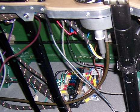
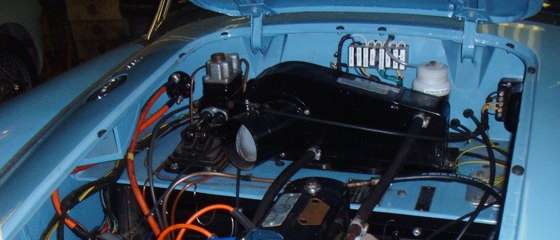
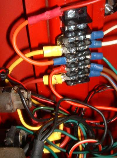
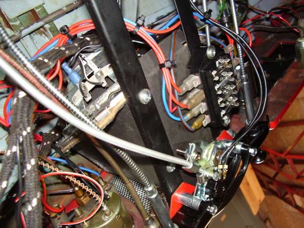
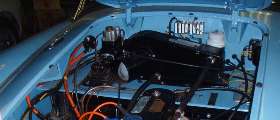
Following are some pictures of recent installations for additional fuses. The red one is not fuses but a barrier strip for joining lots of wires on screw terminals.
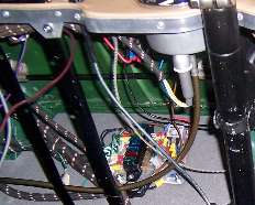

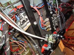
|