The MGA With An Attitude
MGA STEERING RACK TECH DAY - SR-201
June 14, 2003 - Naperville, IL
Photos and notes by Barney Gaylord - MGAguru.com
This thing absolutely will come apart, one way or another.
Click for larger images. - Larger pics average 32KB.
 |
 |
 |
 |
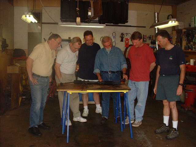
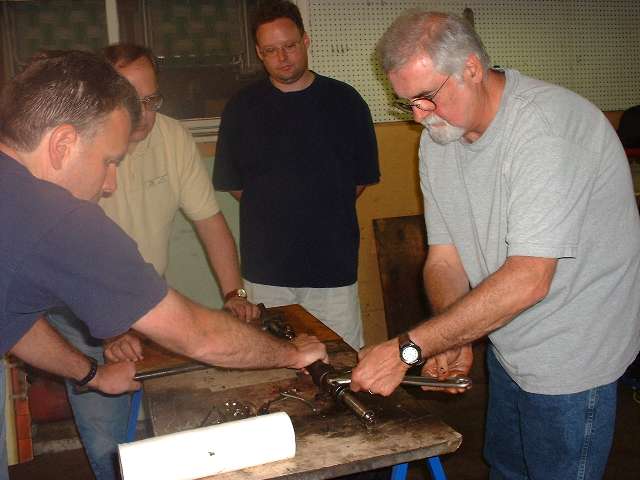
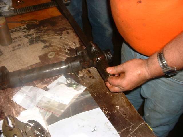
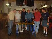
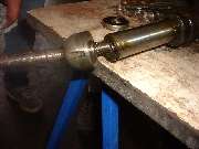
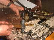
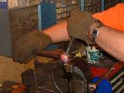
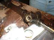
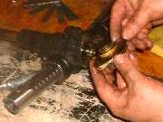
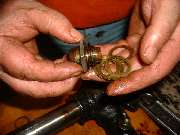
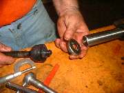
Gathering of the clan at 10 AM on the nicest working day of the year. This job was estimated to only take a couple of hours, as the steering rack was already cleaned up and on the bench, no crawling around the car required. We were about to learn a few new things, including one of the greatest examples of what can go wrong with a simple tech project. Okay guys, start by cutting off those rotten gaiters, then grab some wrenches, and let's get with it. Loosen the jam nut and remove the tie rod end, then remove the inner ball joint from the gear rack.
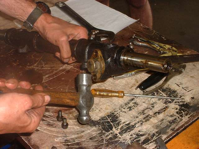
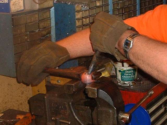
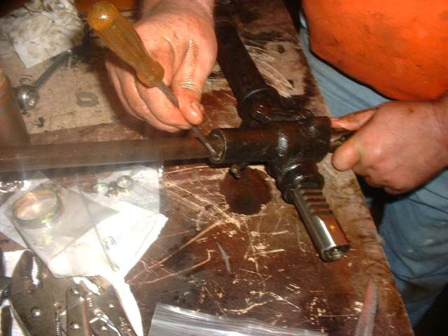
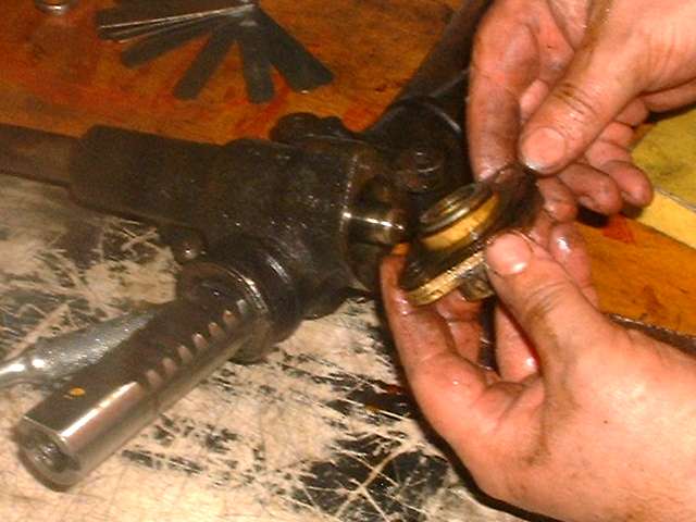
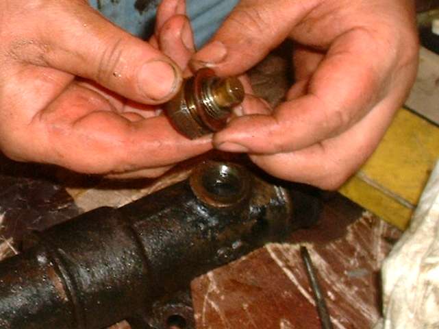
The inner ball joint is secured with a special lock tab cup. The outer edge is peened into slots at the sides of the ball cover, while two tabs at the center engage a wide slot in the end of the gear rack. This serves to keep the ball socket assembly screwed together at the same time it secures the ball joint to the gear rack. Start with a small screwdriver to bend the lock tab up out of the side slots. Then you can use a pipe wrench to unscrew the ball joint from the gear rack. No need for the special keyed female wrench called for in the shop manual. Notice the tab washer on the table behind the rack after disassembly in the first picture below.
|
 |
 |
 |
 |
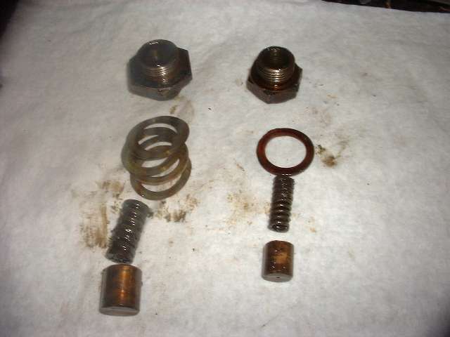
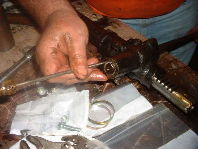
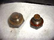
Next we unscrew the damper caps from the top of the rack housing. The larger damper on the left presses on the smooth top surface of the moving gear rack directly over the input pinion gear. This keeps the rack gear firmly in contact with the pinion gear to eliminate any backlash in the gear mesh. Because of the contact angle of the gear teeth, this can require quite a bit of force to keep the gear teeth together during hard steering motions. As such, that damper incorporates a heavy square section die spring, and shims are used to adjust the nut for as little motion as possible in the bronze plunger. The smaller damper on the right is located near the opposite end of the rack. This is basically an anti-rattle device to keep the gear rack from moving around in the small clearance space between the gear rack and the housing. As such the spring is smaller, and the float motion of the plunger is not critical, so it is given enough travel space that it does not need to be shimmed, and a fiber washer is sufficient for sealing the joint.
|
 |
 |
 |
 |
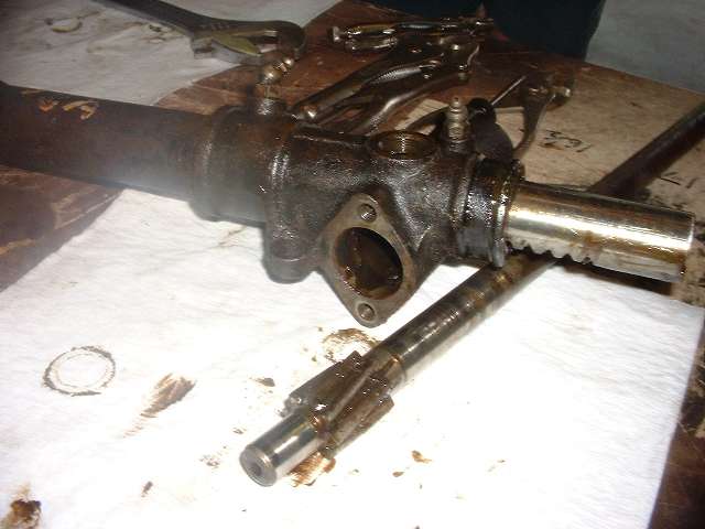
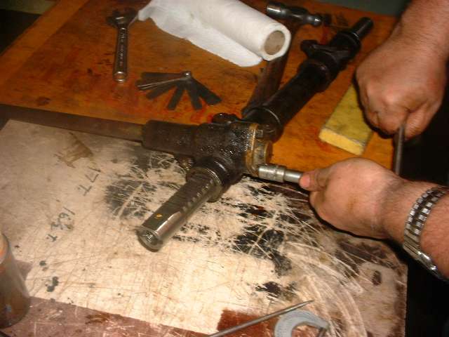
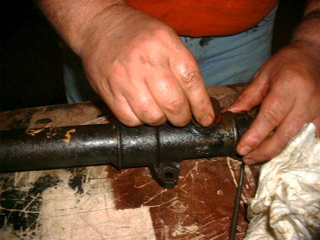
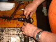
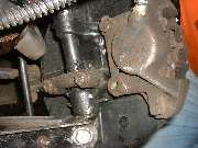
Next we remove the input pinion shaft from the housing. Remove two bolts from the front cover, give it a light rotational tap on one of the ears to break it loose, and it pulls right out (or at least it should without much trouble). Along with the bronze cap you get some shims under the flange and one steel thrust washer that bears against the end of the pinion gear. As soon as the cap is removed the pinion shaft can be tapped forward and removed from the housing. Once the pinion shaft is out the gear rack can be pushed out of the housing. One last part not shown in the pictures above is another steel thrust washer (actually a thick collar) that bears against the hidden end of the pinion gear. This part cannot be removed from the housing until after the gear rack is out. This thrust collar will be seen several pictures farther on.
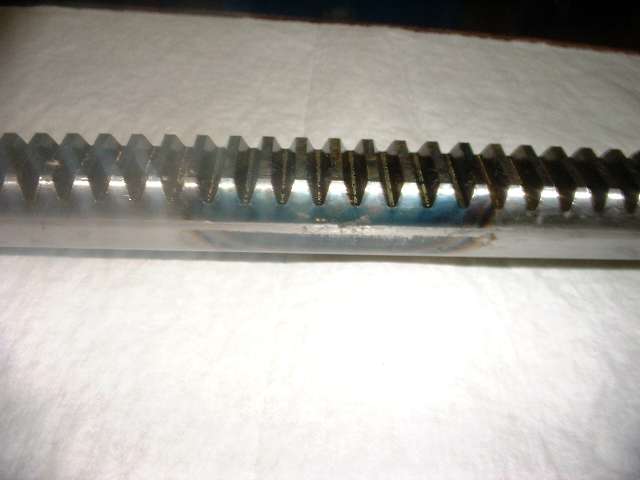
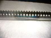
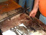
The picture on the right above shows the gear rack after cleaning. You can clearly see where a short section of the gear teeth have been flame hardened for wear resistance (giving the part a blue tint). This is done only in the area where the pinion gear meshes at the direct center of travel of the rack. This accounts for more than 90% of all gear motion, as the steering mechanism spends very little time near full lock.
The bore of the rack housing will usually have very little wear, so it can usually be reused as is after cleaning. If perchance the rack end seals had failed, and the car had been driven a long time with dirt inside the steering rack and no oil, then the housing might be worn enough to cause some concern. Do not confuse a small amount of vertical play in the rack at the pinion end of the large tube with wear. The flat side of the rack where the gear teeth are cut does initially allow more vertical play than you will find at the other end. But installation of the pinion gear will eliminate most of that motion, and proper installation of the larger rack damper will press the rack against the pinion gear to eliminate the rest of the play in the rack.
|
 |
 |
 |
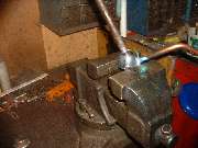 |
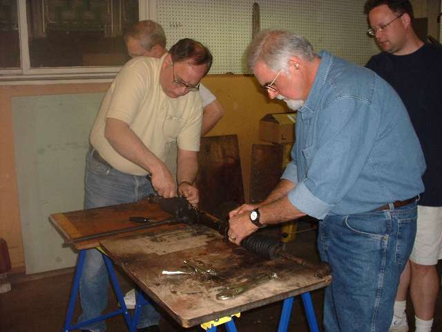
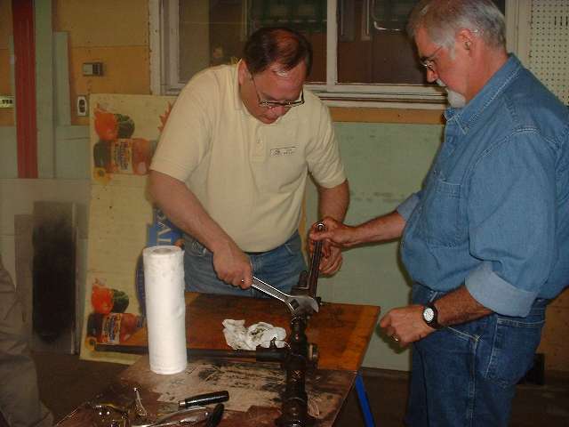
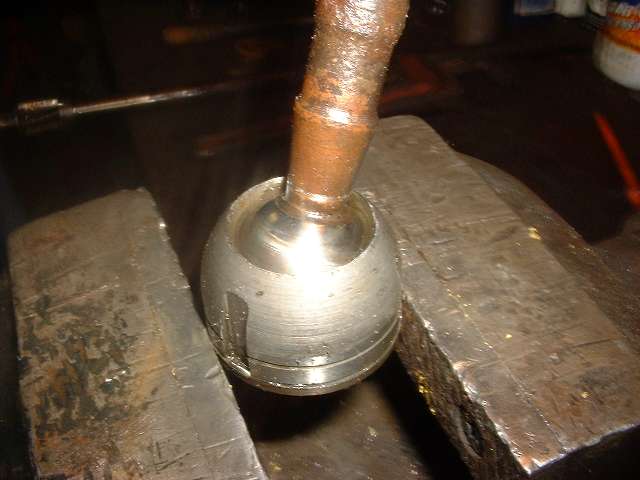
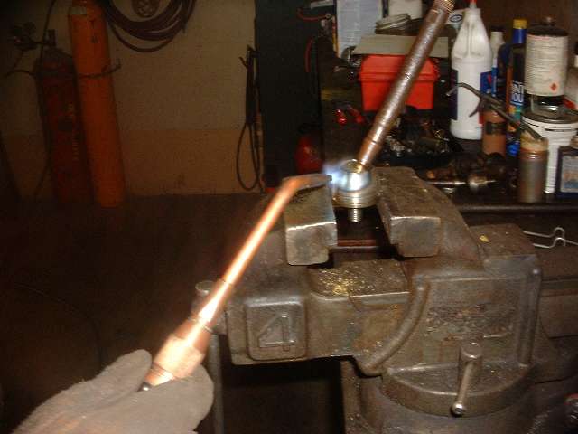
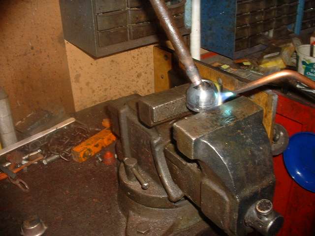
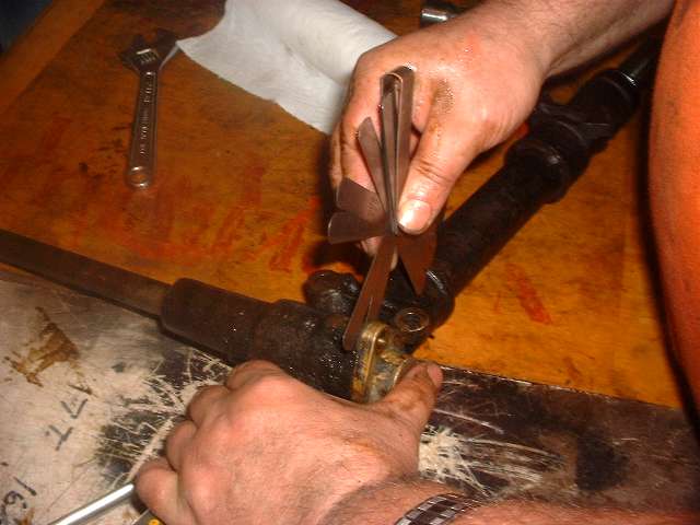
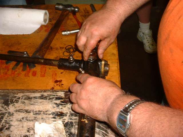
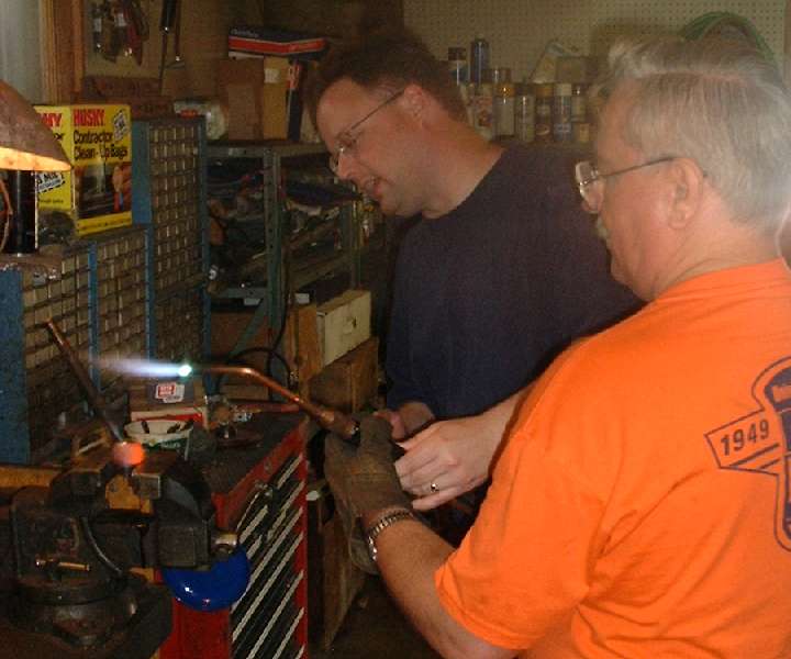
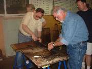
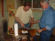
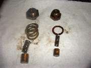
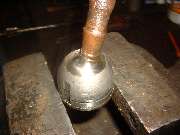
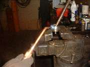
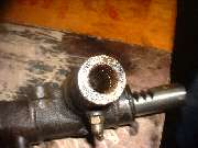
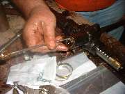
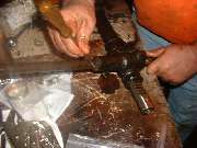
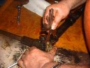
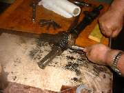
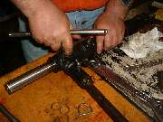
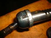
Then came the challenging part of the day, and the part that gave us more trouble than expected. The inner ball joint housing is composed of a large acorn nut screwed onto a shallow threaded base. Slots on the outside of the large nut accommodate the factory wrench for assembly. For the inner part of the socket, the only provision for a wrench is two small longitudinal holes in the back intended for a special tool with a pair of hardened steel dowel pins. By experience, this is no match for the force required to unscrew these parts. I have in the past fabricated and promptly broken the pins (even hardened steel dowel pins) off of no less than three special tools before abandoning the idea of using a pin wrench. This job will likely always require heat to expand the nut before it can be unscrewed. In the process, it is generally convenient to hold the narrow bottom flange of the socket in a bench vise.
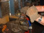
In several prior steering rack rebuilds the inner ball joint nut has always given up its grip with a moderate amount of heat and a firm twist with a pipe wrench, and as soon as it broke loose it would unscrew with little resistance. Not so for this one. This time it took more than few tries, each time heating it more and wrenching it sooner while it was still very hot. We even let it cool down once and started again with the intention of heating the nut quickly and removing it before the inner part would get too hot. With sufficient heating (lots of heat) it did finally give up and unscrew, but with a great amount of resistance while turning, and the threads took a beating and were galled up a bit in the process. When the second one also did not come loose on the first try we decided to leave it alone, as it was really a nice snug fit for the ball joint, and the demonstration on the first one would suffice for the learning curve.
More recently a net friend suggested similar heat, but using a cold chisel (wedge nose punch) and hammer to rotate the cap after heating. It is noted that the pipe wrench may tend to smash the cap inward to bind on the threads, but the punch at a tangent may likely be able to knock it loose without a similar squeezing. Also in case the thin flange on the male threaded base is deformed by the vice, it would be prudent to grind or file the flange flat to remove any burrs before reassembly.
|
 |
 |
 |
 |
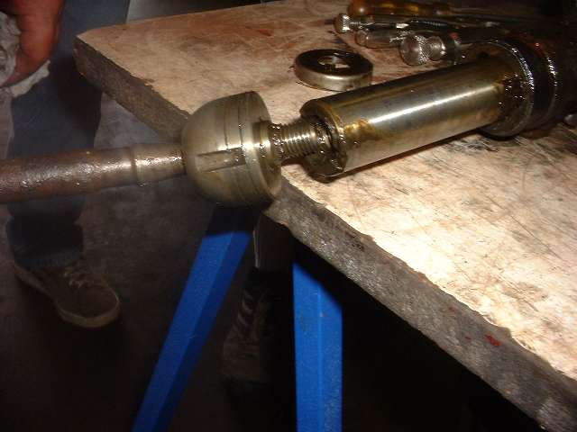
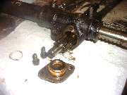
In the second picture above you can see what remains of some shims. These shims always seem to be aluminum (factory original I presume) rather than the traditional brass we might otherwise expect. Heating with the acetylene torch will nearly always damage these aluminum shims, so they may not be reusable. If the ball joint has worn to be a little loose it will require removal of one or more shims to bring the two parts of the housing closer together to remove the clearance around the ball. Too few shims make the ball joint tight. Too many shims leave it loose. The idea is to end up with as little working clearance as possible without binding.
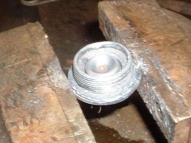
Notice that the spherical socket in the base of the housing is a separate removable part, like a small button. If you happen to be getting close with the shimming adjustment, but do not have exactly the right combination of shims on hand, you can do a little creative hand fitting. You can use the flat side of a grinding wheel to face off the end of the acorn nut to allow it to screw together a little farther to tighten the socket on the ball. If the ball fit happens to be too tight, you can grind off the flat back side of the button to open up the socket housing slightly. This is a bit more labor intensive than using the proper shims, but in a pinch it may allow you to finish the job immediately rather than setting it aside until you get the right parts.
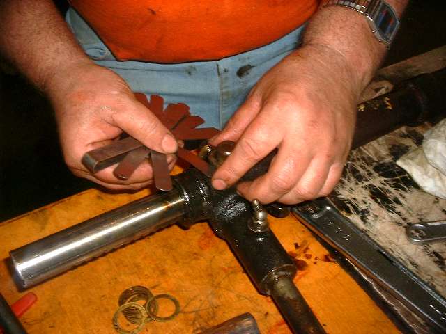
Another obvious solution to the shim problem is to make your own shims from thin shim stock. Cutting the center hole may take a little finesse, but the OD can be cut with a good pair of scissors if you use brass shim stock. A few sheets of various thickness of thin brass stock are a nice thing to have around the shop.
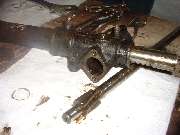
In the third picture above you can see the thick thrust collar assembled on the pinion shaft just above the pinion gear This is the small part that has to be installed in the housing prior to insertion of the gear rack. It has a small slot on one side which the book says should face away from the pinion gear. I have my suspicions about that note. I always though the slot should face the pinion gear to serve as an oil passage to encourage development of an oil film in the working joint. I seriously doubt that it makes much difference one way or the other, but I will for now concede to the good book. If anyone has a good idea about this, do tell.
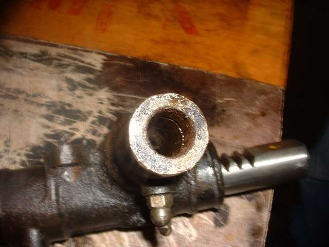
The last picture above is a view into the input side of the pinion shaft housing. This is the journal bearing area with the grease fitting. Just inside the opening is a pair of identical grooves which you may not notice until you spend some time digging out the old felt seal and some hardened grease. Even though the book calls for a single seal to be installed here, with a little patience you can install two felt seals. If you keep this joint properly greased there is likely little chance of much dirt getting in, but the extra seal might help keep the grease from getting out and maintain a cleaner machine. These felt seals are relatively cheap, and you are likely to bodge a couple of them with your first installation, so it's a good idea to have a couple extras on hand.
|
 |
 |
 |
 |
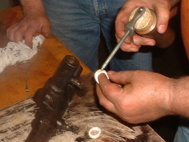
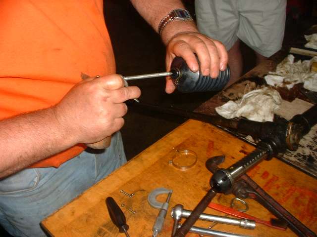
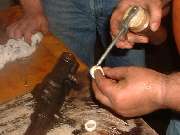
The installation of the felt seal is not as simple as it sounds. It has to be folded out of round to get it into the hole and then pushed and expanded again into the slot in the bore. Having tried it dry and/or oiled, I have some casual observations. It is easier to install wet, but when soaked in oil the seal is also easy to tear into shreds when inserting the pinion shaft. I find the most practical combination is to install the seal dry, then add just a light wipe of oil down the bore to dampen the surface a bit, and generously oil the pinion shaft before pushing it through the seal. As the shaft end is entering the seal area it helps to use a small screwdriver to depress the felt seal into the groove to allow the shaft to pass through without tearing up the felt. This chore is a little tedious, so I suspect the factory assemblers probably had a bullet nose pilot tool to pass through the bore just ahead of the pinion shaft as it was being installed.
More recently a fellow being greatly frustrated with attempts to install the felt seal reports using a rubber o-ring its place. I do not have the groove dimensions handy, but I do know the requirements for an o-ring seal. In general the groove depth should be 2/3 of the sectional diameter of the o-ring, and the groove width should be 3/2 as large as the thickness of the o-ring. Next time I find the need to tear into one of these things I will get the details for a substitute rubber o-ring.
Addendum, January 2007: John Treible (Newsletter Editor, The Emerald Necklace MG Register) wrote:
You mentioned the possibility of using an o-ring. The size I settled on was I/D 3/4" O/D 1" Section 1/8". I was able to easily install both the inner and outer o-rings in a matter of minutes. I oiled the o-rings and then tried to install the pinion shaft. Met with quite a bit of resistance and had to use a wooden mallet to force the end of the shaft through the o-rings. In doing so the inner o-ring was damaged so I had to install another one. This time I generously lubricated the end of the pinion shaft with a healthy dose of Vaseline. The pinion shaft did need a little persuasion from some gentle taps of the wooden mallet but the toothed end did go through this time with no damage to the o-rings.
|
 |
 |
 |
 |
Be forewarned as I said before, the wide thrust collar for the pinion gear has to be installed in the housing before the gear rack. If you forget this part and have the pinion shaft installed before you discover the misfit, you will be in for disassembly and starting all over again. Remember that pesky felt seal? Pay attention next time. Assembly sequence is wide thrust collar first, then the gear rack, pinion shaft, steel thrust washer, and then the bronze cap.
The second picture above shows the pinion bearing cap installed with no shims. Holding it firmly in place you can measure the resulting gap behind the flange with a thickness gauge. Then put together a stack of shims that is 0.001 to 0.003 inches thicker than the gap. After final assembly with the shims the pinion shaft should have minimal end float, no more than 0.003 inch, but should not be tight. No cheating allowed here with a large end float, as that allows play in the steering wheel because of the helical pinion gear. However, I have found that reusing the original shim stack will often work well, as there is generally not much wear in the area of the steel thrust washers.
|
 |
 |
 |
 |
Now we get on to the main rack damper. Start by removing all of the shims from the nut (and you might expect a rather large stack of thin shims). If you are reusing the original brass damper pad you will probably notice a wear mark across the end that matches the radius of the gear rack. A new part starts flat on the end but will wear quickly to this profile (at least a small amount) soon after initial use. If the old part is not worn too much to use with proper shimming, the old one may be better than a new one, because it has more surface contact area and will have less future wear. To use the old damper pad, first align the wear mark with the travel direction of the rack so the part will drop as far as possible into the hole. Install the brass plunger (damper pad), die spring, and the larger cap nut with no shims.
Gradually tightening the nut to compress the spring will give a small amount of drag to the moving rack, but you should still be able to turn the pinion shaft with one hand. When the nut comes to bear directly against the brass pad the rack will suddenly bind, and prevent you from turning the pinion shaft. Back the nut off just enough to regain free motion of the rack. Run the rack through full travel in both directions to be sure there will be no binding. The intention here is to have minimal end clearance for the damper pad without binding. Then use a thickness gauge to measure the space under the flange of the cap nut. Assemble a stack of shims which is 0.002 to 0.005 inch larger than the measured gap, remove the nut, install the shim stack, and reinstall the nut. After tightening the nut check again for free travel of the rack through full travel in both directions. If it binds anywhere along the travel, add another shim for the damper cap nut. When reusing the old damper pad you may likely remove several shims from the original stack. If someone else had done that in the past, and you are now installing a new damper plunger, then you may have to add several shims to the stack.
|
 |
 |
 |
 |
Installation of the secondary rack damper (smaller one) is much simpler. Just assemble the cap nut, the spring and the damper pad, install a new fiber washer (or the original one if it's still in good condition), and screw the thing into place. Check again for free motion of the rack, but there should never be any problem here.
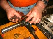
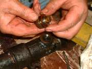
Time to install the tire rods. Place the lock tab cup washer on the inner ball joint before screwing the ball connector into the rack. As you tighten the ball joint to the rack, align the central tabs of the cup washer to nest in the slot in the end of the gear rack. Tighten the ball joint securely to the rack. This does not have to be terribly tight; one good pull should do, as the lock tab will serve to prevent its undoing. Use a flat nose punch to knock the lock tab flange down into the side slots of the ball nut. This serves to retain assembly of the ball socket as well as securing it on the rack.
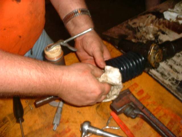
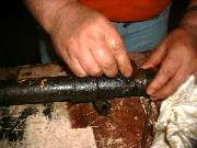
Almost finished now. When installing the rack end seals a touch of oil inside the small ends of the rubber boot will allow it to slide easily over the tie rod. Position the small end of the boot into the groove on the tie rod, the large end of the boot into the groove on the rack housing, and install the band clamps. As a matter of courtesy to the next person who will some day have to replace these boots with the rack in the car (perhaps even you), please give consideration to the access direction for the screw heads on the band clamps. For the MGA, the screws heads for the larger band clamps should point straight down at the front of the rack. The smaller band clamps can be installed in pretty much any orientation.
|
 |
 |
 |
 |
Once the end seals are in place you can install the specified 6 to 8 ounces of gear oil into the rack housing. For the MGA the oil can be injected through the Zerk fitting on top of the main housing near the pinion shaft (but not the fitting directly over the pinion shaft). Move the rack to full lock in both directions, when you can hear oil gurgling through the end boots you have enough. The same technique is used to determine fill level on the car. Do not overfill the rack, as this may cause oil to be forced out past the ends of the rubber boots in operation. Lubricate the pinion journal bearing with several strokes of a grease gun at initial assembly, but in operation only two strokes every 12,000 miles.
Installation of the tie rod ends is standard fair. If you counted the turns when removing the old ones you can screw the new ones on the same distance as a good setup starting point. Some replacement tie rod ends might be a slightly different overall length, so don't count on having perfect toe in after initial installation without a fine tuning adjustment on the car.
|
 |
 |
 |
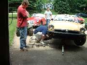 |
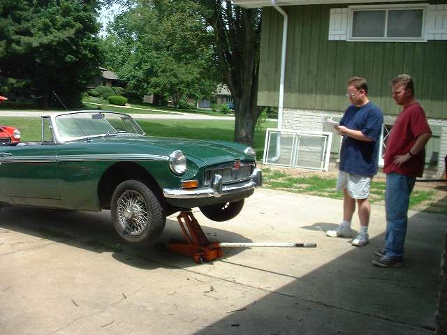
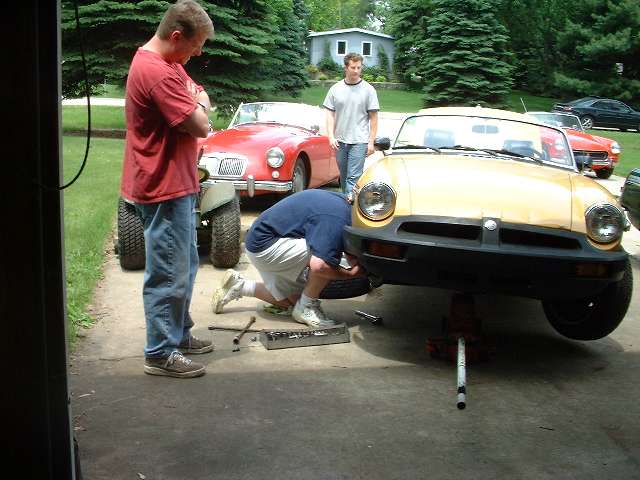
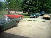
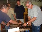
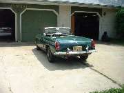
If you were wondering what the MGBs are doing on this page, that's just the way club tech sessions go, as we often get into some interesting side shows. The green car had a distinctive nose down list to the left and a slight tail lift. New leaf springs were the cause of the high tail problem. Jacking up the center of the rear axle didn't help the list. Jacking up the center of the front cross member did make the car level out. Nothing broken or bent up front, so a new set of front springs may be the subject of a future tech session.
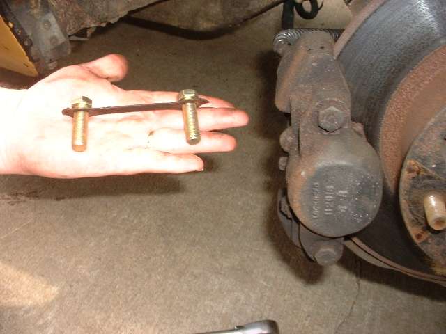
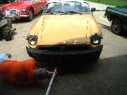
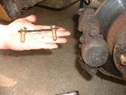
The yellow car had a nasty problem with a loud clunking noise in the front end that would go away with a press on the brake pedal. That turned out to be a brake caliper with one mounting bolt missing and the other bolt very loose. A few more miles on the road could have led to disaster. The embarrassing part is that it had a perfectly good lock tab that was never bent over against the bolt heads. A pair of new bolts out of stock and a finishing tweak on the lock tab put that one back in order.
Just about that time, when most people were leaving, that orange Midget in the background (last picture) ventured in slowly under hand brake control and no brake pedal pressure. Its original intent was an emissions tune up after failing the Illinois Air Test, but we had to bleed the hydraulics to restore the brakes first. Seems like it was losing fluid and would soon need some cylinder rebuilds. Also the exhaust down pipe had to be reattached to the manifold with a new gasket and a hand full of new hex nuts, which is not easy access on this car. Finally under the bonnet, there were multiple problems with the carburetors, stuck choke, misadjusted mixture nuts, high float level, one sticky float valve, and excessively high fuel pressure causing occasional fuel overflow. Otherwise the tune up finally went okay (whew). A fuel pressure regulator was installed later, and a sniff with the CO sensor at the club meeting a couple nights later pronounced it to be ship shape for the air test.
Then it was back to the green MGB for some tune up work. The distributor drive was far enough out of phase to make timing alignment next to impossible, so a little time was spent to R&R the distributor drive gear to set it straight. And there was a little fussing to straighten the distributor clamp plate before reassembly. Again the tune up was the smaller part of the problems at hand. With all these different projects going on, the planned three hour steering rack tech session which started at 10 AM was finishing up about 10 PM. But so it goes when a bunch of enthusiasts get together for another tech day.
|
|
|