The MGA With An Attitude
STEERING SHAFT ALIGNMENT and Rack Shims - SR-113
On 11/4/2009, "msd2x" wrote:
>>"I could not find the description and price of the steering column alignment tool for properly setting the steering rack. If you still supply them ....".
I am not "in the business", and I sell nothing. I don't recall mentioning any such item on my website, As far as I know there never was such a tool issued by the factory for the MGA. Instructions for aligning the steering column and shimming the steering rack (if necessary) are given in the Workshop Manual, Section J.9.
There is such a tool listed by Moss Motors USA for use with the MGB. See Moss Motors part number 453-622. Supplemental Instructions for its use can be found here:
https://mossmotors.com/media/instructions/453-618_453-619_453-628_453-627_453-638_980-290_INST.pdf.
 Since MGA and MGB use the same steering u-joint, it should work the same on the MGA. I have (until now) had no reason to mention it on my MGA web site, as it is not required to service the MGA (and I'm not sure why it would be needed for the MGB). Instructions for aligning the steering column and shimming the steering rack (if necessary) on the MGB are given in the Haynes MGB Repair Manual, Chapter 11, Section 23, paragraph 4. This also makes no mention of any special tool required. The factory special tool 18G1140 is mentioned in an earlier section 20 referring to the late model energy absorbing steering column.
The instruction, in general, is to assemble everything (rack and column) with loose fasteners, then tighten the u-joint bolts first, followed by tightening the steering column bottom flange bolts and then the column top cradle bolts, in that order. If there are any gaps between the rack and frame mounting points, install shims to fill the gap (usually one point only if any), then tighten the bolts. Last step is to loosen and re-tighten the column bottom end flange bolts to allow the column to float and self-align, just in case the shimming process may have changed alignment of the rack input shaft.
The "special tool" sold by Moss is a pair of concentric cone tip pointers to be attached to the two shafts. The idea is to align the shafts to make the pointers coincide at the same point in space. That would make the shaft centerlines intersect at the central point of the universal joint, thereby leaving no side load on the shafts. I suppose this is particularly important for the collapsible steering column to avoid friction for collapsing parts (or possibly to avoid damage to the collapsible parts during normal use).
Following instructions in the manual for the non-collapsible steering column, is should be sufficient to install the u-joint first for alignment of the shafts, then install any shims that may be required. For the MGA and early MGB bottom end of the steering column is floating, so the u-joint will do the column aligning before final tightening of the bolts. I guess the factory was particularly concerned about having absolutely no side load on the collapsible steering column parts in late model MGB.
As usual, there is a way to make a simple tool at home to perform the same function as the factory special tool. Wrap a stiff wire several turns around the shaft and position the tip of the wire near the shaft axis beyond end of shaft. Ditto for the second shaft, leaving the two wire tips close together. Rotate one shaft to observe wobble of the wire tip. Bend the wire as needed to adjust position of the tip (closer to the axis of rotation) until it does not wobble when rotating. Ditto for the second wire. You then have fixed concentric pointers that will serve the same function as the special tool.
When I disassembled my MGA in 1977, there was one horseshoe shim with a tail tab (not original factory type) that fell out from somewhere, either steering or suspension. Also there are no holes drilled in the frame at the rack mounts, so never any original shims from the factory. When I reassembled the suspension and steering rack a few months later I could not find any place in need of a shim, so I left it out. Finally installing the steering column (9 years later in 1986), the column end did easily self-align with the pinion shaft, so still no shims required anywhere. I have repaired or rebuilt the rack in-situ a couple of times, but have had no reason to dismount the (still original) rack housing from the frame in the past 230,000 miles.
The chassis frame was obviously jig welded at the factory, and same for the steering rack housing, so all mating parts should have been in a common flat plane, needing no shims when new. Use of the shims would be some concern if there may have been any warping from thermal distortion during original welding processes, or if there may have been some damage in use in later life, or possibly if a replacement steering rack does not have exactly the same shape as the original part.
 As for the shim, illustration at right is from the Service Parts List. Instruction for the shim is to use it to fill a gap, if any. Most commonly there will be no shims needed, sometimes just one. When a shim is used (usually factory installed), a hole should be drilled in the frame and a rivet installed to secure the shim permanently. This is obviously a correction for some misalignment (possibly thermal distortion) in welding of the frame.
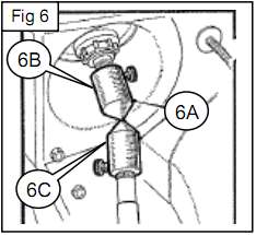
Another small oddity has come to my attention here. The SPL calls for a Nyloc lock nut in front and standard flat nut in back (and I have no idea why). The front bolt is then 1/8-inch longer than the rear screw to accodate the taller Nyloc nut.
|