The MGA With An Attitude
Universal Joint REPLACEMENT SEQUENCE -- PS-202
Before you attempt replacement of the propshaft U-joint, you should watch the YouTube video by John Twist of University Motors, Ltd. This web page gives a blow by blow description of what John is doing, with added diagrams to show where things rest and where things are hit or pressed. Also note the John has a tool list as follows.
1.) Brass faced hammer (about 16 ounces)
2.) Special tool, old U-joint cap ground smaller on one end to fit inside of the assembled snap ring.
3.) Special tool, bolt with jam nuts, ground head similar to prior tool but longer spacer.
4.) Snap ring pliers.
5.) Small socket for grease fitting.
7.) Large socket to fit around U-joint bearing cap.
8.) Long punch to back out bearing cap if it goes in too far.
9.) Work bench and Bench vice with at least 6-inch opening.
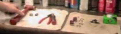
In addition to gathering tools there was a little more prep work. The U-joint was disassembled with extra grease pushed into the bearing caps, and the caps, spider, snap rings and grease fitting are all arranged in handy locations.
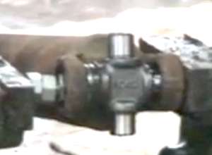
Above is a diagram of the assembled universal joint. Piece parts begin with a fixed yoke welded to the propshaft (providing the fixed axis), an articulated yoke mounted on the free axis, a cross spider with four small bearing journals, four bearing caps with full compliment needle roller bearings inside packed with grease, four snap rings, and the grease fitting to finish it off (more on that later).
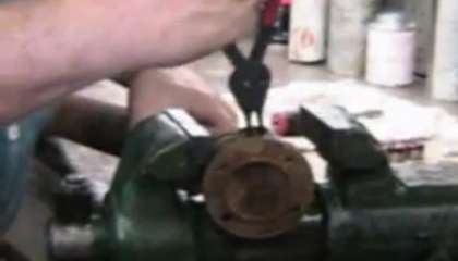
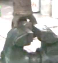
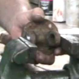
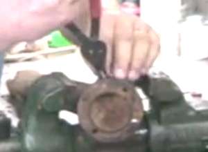
The first operation is to loosen the bearing caps and remove snap rings. Use the special tool to push hard (squeeze in vice) on one end of of a bearing cap. This will compress all the assembled parts together to leave a tiny bit of end clearance to make snap ring removal easy. Above left shows squeeze on the fixed axis cap. Above right shows squeeze on the free axis cap.
In the video you see John first striking the screw arm to tighten the vice, then striking the front jaw of the vice to put a final shock on the vice jaw to break loose a stubborn bearing cap. After squeezing one side remove the snap ring (both axis), then squeeze the other side enough to remove the other snap ring (both axis). Get four snap rings out before going farther.
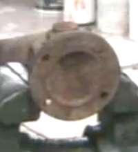
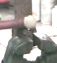
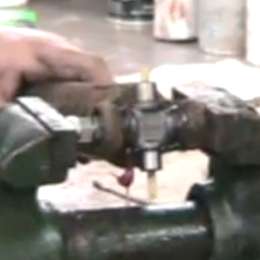
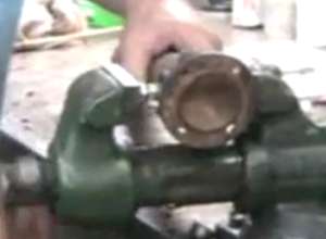
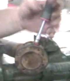
Next adjust vice jaws to suitable width to lay the ears of the fixed axis yoke on the vice jaws. Place the large socket on top of the free yoke surrounding the bearing cap, and strike with hammer as required to move the yoke downward off center, thereby raising the bearing cap partially out of the yoke.
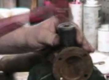
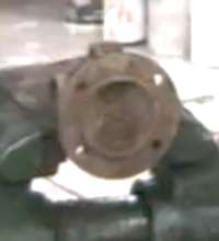
Invert the propshaft and repeat the same operation on the opposite end of the free axis, raising the second bearing cap partially out of the yoke. At this point you need to grip the exposed end of the bearing cap in the vice and tap the side of the weld joint to extract the bearing cap from the yoke, both sides. Then the free yoke can be removed from the remaining spider.
Operation for the fixed yoke is similar. Adjust vice to lay the two exposed journals of the spider on the jaws. Place the large socket on the yoke surrounding the bearing cap, and strike the socket to drive the yoke downward to raise the cap partially out of the yoke.
Invert the assembly and repeat for opposite side, again driving the yoke downward with socket and hammer to raise the bearing cap. Then use the vice to grip the bearing caps to knock them out of the yoke, and extract the spider.
For reassembly, insert one of the bearing caps into the fixed yoke. Use the vice to press it part way in, getting it started straight before you apply too much force. Press it only about half way in, then insert the new spider into the yoke and seat it in the bearing cap. If you press the bearing cap too far in the spider cannot be installed. In that case use a long punch from far side to tap the bearing can back out a bit.

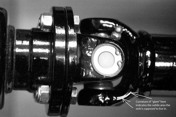
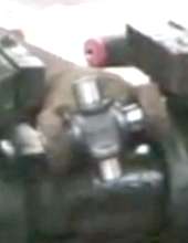
One important detail here. Note the heavy (red) marks in the image above right. There is an indented notch in the fixed yoke to provide clearance for the grease fitting. The spider must be aligned properly to place the tapped grease port in the same position (as shown). If you get this wrong the grease fitting cannot be installed, or the grease gun nozzle will not fit on the grease fitting. See incorrect positioning at right.
With the first cap and spider in place, press the bearing cap home. Use the special tool to press the cap inward just past the snap ring groove, then install this first snap ring. Do not let the spider fall free in the process.
With one cap and snap ring in place, insert the second bearing cap in the yoke and press into place. Get it started straight, and push it half way with the vice. Then use the special tool to push the cap hard home past the snap ring groove. In the video you see John again striking on the screw lever to get the vice very tight. Then install the second snap ring.

Installing the free yoke is similar, but it has one additional problem. The sides of the yoke are angled on the outside, not parallel, so it requires a little additional finesse to get the bearing caps started straight. Insert the first bearing cap into the yoke, then press it gently as required to get it pressed in on the correct axis. If it binds and doesn't want to go in, it is probably a little crooked. Take a good look at the alignment, giving it a squeeze on the "high side" of the cap to straighten it out as you go. Press it about half way in. Again, if it goes too far in the free yoke cannot be installed, in which case you use the long punch to move the bearing cap back out a little.
With the first bearing cap half way into the free yoke, install the yoke onto the spider and seat the bearing journal into the bearing cap. Press the cap (carefully) half way in with the vice, then use the special tool to squeeze the cap farther in past the snap ring groove. Install the snap ring, and do not drop the spider out of the bearing cap in the process.
Rotate the yoke and insert the second bearing cap in opposite side. This requires a little more finesse, again because the sides of the free yoke are not parallel. This is where you should use the second special tool, placing the two tools on opposite sides and on the ends of the bearing caps. This will help to keep the bearing caps straight and parallel. Neglecting to use two flat face driver tools could result in misalignment of spider and/or the last bearing cap. When that happens it is rather likely that you might dislodge one of the needle rollers.
If a needle roller gets crossways and sticks between the end of the journal and inside of the bearing cap, the cap cannot be pressed all the way in, and the snap ring cannot be installed. Then you get to go back to the first disassembly step and knock the bearing caps out of the spider. Retrieve the errant needle roller from inside the bearing cap, put it back in place in line with the other needles, and try not to get any dirt inside. If it gets dirty you need to remove the needle rollers (don't lose any), wash it all in cleaning fluid, dry the parts, install more grease and reassemble the needle rollers inside the cap. Do not even think about assembling it with one missing roller, as it would not last long in operation.
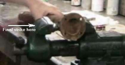
Once the last bearing cap is pressed hard home you can install the last snap ring. Then you can seat the bearing caps hard against the snap rings for final centering. Hold the propshaft in your hand. Strike smartly with the hammer radially on the weld in line with each of the four bearing caps. The shock will move the yoke relative to the spider (due to inertia), pressing the bearing caps outward against the snap rings. Once done the U-joint should move freely on both axis with finger force only. It can be just a little stiff and should not be sloppy loose when new.

Last operation is to install the grease fitting. Assuming the U-joint was packed with grease during assembly it should not need any additional grease at this time.
|