The MGA With An Attitude
CM-201 is a more advanced course for the problems of cam timing and valve clearance from internal engine parts. This is important if you increase compression or use a high performance camshaft. Sorry about the glare on the dial indicator here. Maybe I'll get a better picture later.
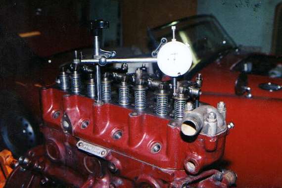
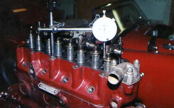
The picture above shows the indicator set up on the #1 exhaust valve with the valve closed (up). Since the valve will be traveling downward during operation the indicator must be preloaded to at least half of its maximum of 1" total travel. The picture immediately below shows the same valve fully open (down). The difference between the before and after readings on the indicator is the total travel (lift) of the valve.
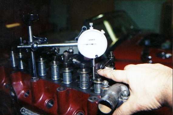
Now the picture below shows my fat finger depressing the rocker arm until the valve hits something to check the amount of clearance for the valve head. In this case the valve head will hit the top of the engine block just a short distance beyond where it attains full lift. For a stock MGA engine (not twin cam) with all original type parts this will be about 1/8", but this depends on the condition of the valves, the valve seats, thickness of the head gasket, and how much the head has been shaved over the years. If you shave the cylinder head, this clearance diminishes. If you install a high lift cam, this clearance diminishes. If you install high ratio rocker arms, this clearance diminishes. At some point you may (will) discover that you do not have sufficient clearance left for safe operation of the engine.
It is recommended that you have at least .080" clearance for the intake valve and .100" clearance for the exhaust valve between the valve head and the piston at the point of closest approach. For an MG engine with dished or flat top pistons this is no problem, as the clearance there is about .400" in stock form, which will accommodate lots of extra valve lift and head shaving. The problem with these engines is that the valves, and the exhaust valve in particular, overlap the side of the cylinder bore and will come down on top of the engine block if they open very much farther than the original amount. Here the minimum clearance from the block at full lift should be at least .060" for the intake valve and .080" for the exhaust valve. |