PART NO. SPL.PAGE DESCRIPTION
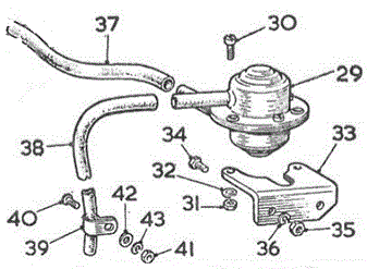
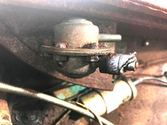
AHH5903 TC.C.1 29 Relief valve and cage assembly -radiator -(cooling system, Twin Cam)-
Com.(C)652 also 575, 613, 623, 633, 648
PMZ0308 TC.C.1 30 Screw fixing valve to bracket (2)
FNZ103 TC.C.1 31 Nut for screw -(relief valve to bracket (2)
LWZ203 TC.C.1 32 Washer for nut (spring) (2)
AHH5906 TC.C.2 33 Bracket -valve -(cooling system, Twin Cam) Com.(E)652 also 575, 613,
623, 633, 648 -was ARH1022
HZS0404 TC.C.2 34 Screw -fixing bracket to body (2)
FNZ104 TC.C.2 35 Nut for screw -(bracket to body (2)
LWZ204 TC.C.2 36 Washer for nut (spring) -bracket to body (2)
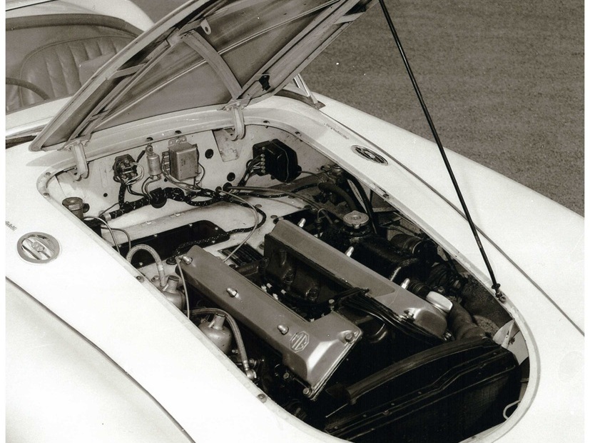
AHH5905 TC.C.2 37 Hose -header tank to valve -(relief, cooling system, Twin Cam)-
Com.(E)652 also 575, 613, 623, 633, 648
AHH5907 TC.C.2 38 Tube -overflow -(relief valve, cooling system, Twin Cam) Com.(E)652,
also 575, 613, 623, 633, 648)
PCR0607 TC.C.2 39 Clip -overflow tube -(relief valve, cooling system, Twin Cam)-
Com.(E)652 also 575, 613, 623, 633, 648
PMZ0306 TC.C.2 40 Screw fixing clip to body -header overflow
FNZ103 TC.C.2 41 Nut for screw -clip to body
PWZ103 TC.C.2 42 Washer for nut (plain) -clip to body,
LWZ203 TC.C.2 43 Washer for nut (spring) -clip to body,
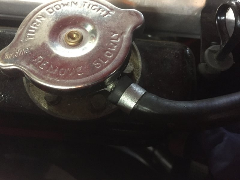
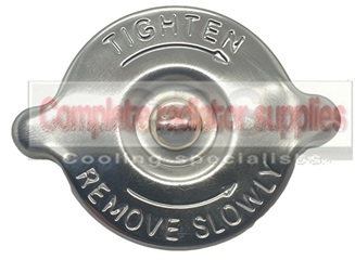
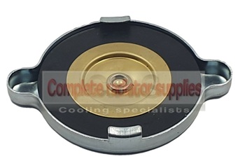
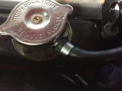
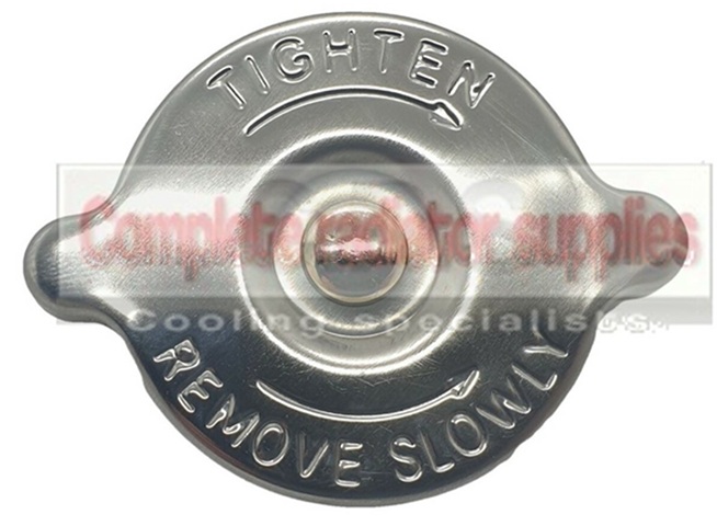
The AHH5904 Cap is to be installed on the AEH593 header tank when the remote pressure relief valve is used. This cap is similar to a pressure relief cap, except that it is completely sealed and does not incorporate any pressure relief mechanism.
 > >
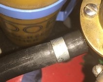
The AHH5905 Hose is item 37 in the drawing illustration. It connects the header tank filler neck to the remote pressure relief valve. As original, this hose would include two zinc plated steel tubular ferrules that serve as hose clips. The ferrules must be installed on the hose before the hose is pushed onto the tube fittings.
It is important that all of the mating parts must have correct as-original dimensions for this to work as a pressure tight push-on fitting.
|
 >
>