The MGA With An Attitude
VACUUM LINE ROUTING - IG-121
Common question: How do you install the vacuum line from carburetor to distributor?
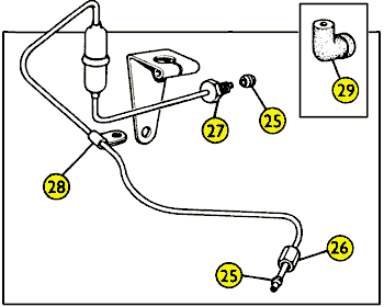
When you buy a "pre-bent" vacuum line for MGA (or early MGB) it may look something like this illustration. This does not show all of the bends, correct orientation of the end fittings, where it follows around the engine, or where it connects at the ends. There should also be a small bolt and nut running horizontally through the bracket to pinch onto the bulb. Item 29 is an optional rubber connector used for the later MGB style vacuum advance unit with push-on connector.
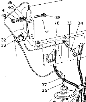
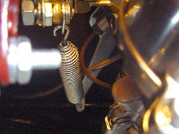
The metal pipe should be all one piece from carburetor to distributor with a fuel separator bulb in the middle. The bulb is filled with wire wool with the metal pipe on each end to serve as a fuel separator. The bulb goes upright with bottom end connected to carb and top end connected to dizzy. The bracket holding the bulb was originally mounted on the second manifold bolt from back. However, with engine in the car you may find it easier to install the bracket on the rear manifold bolt. The P-clip goes on the rear head stud. Use a second nut there if the stud is long enough. Otherwise you have to R&R the nut to install the P-clip.
Illus#   Part#   Description
	AUC4490  Union, automatic ignition, rear carburetor
32	 1H830   Pipe, vacuum ignition control (with fuel trap)
32	 1H919   Pipe (new part number)		Com. (E) GB11301
34	 2K6192  Nipple, carburetor end		Fin. (E) GB11300
35	 2K6193  Tube nut, carburetor end	Fin. (E) GB11300
35	 2A459   Tube nut (new part number)	Com. (E) GB11301
36	 6K649	 Olive - Qty 1/2 - (qty increased at (E) GB11301
37	 6K650   Tube nut, distributor end
 Item 34 in the illustration above was originally a long brass nipple soldered to the pipe, using a female threaded flare nut. Details of that pipe end and the required adapter fitting can be found in tech article CB-125 in the Carburetor section. Item 34 in the illustration above was originally a long brass nipple soldered to the pipe, using a female threaded flare nut. Details of that pipe end and the required adapter fitting can be found in tech article CB-125 in the Carburetor section.
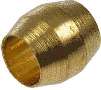 After 11,200 engines (October 1956) the soldered fitting was changed to the small brass olive, and a matching male threaded compression nut.
The current Moss Motors replacement pipe has a male threaded nut and brass olive (items 27 & 25 at top of page).
After 11,200 engines (October 1956) the soldered fitting was changed to the small brass olive, and a matching male threaded compression nut.
The current Moss Motors replacement pipe has a male threaded nut and brass olive (items 27 & 25 at top of page).
These fittings are not interchangeable, because the female threads in the throttle body are different.
To use the Moss Motors pipe with the early style adapter fitting you can remove the end fitting from the Moss pipe and install the original female threaded compression nut and soldered flare fitting.
|
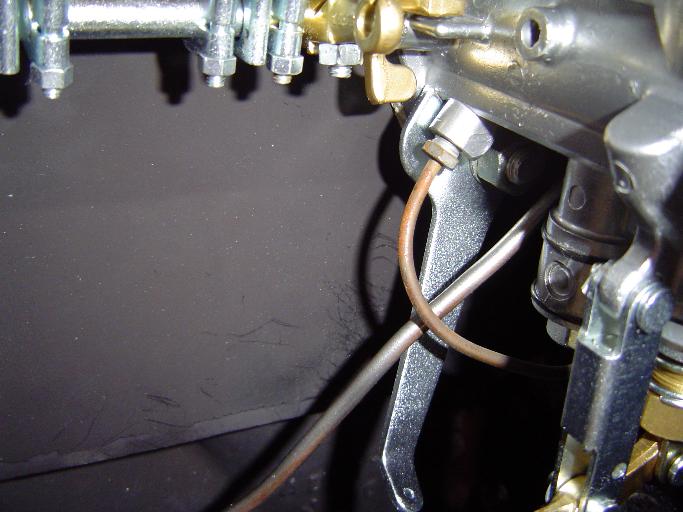
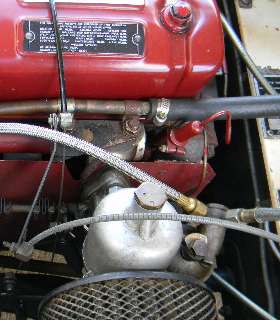
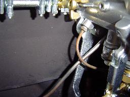
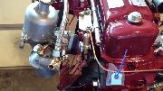
Photo at right below shows the fuel separator bulb and bracket correctly on the second stud from the back. However, the lower tube is incorrectly turned back upward to run over the top of the heat shield before going underneath the carb. This was claimed to be an original MGA 1600 survivor car with low mileage, but it appears to have been "tampered" with in various ways. The valve cover was repainted (poor masking job on the patent plate), the firing order plate is missing (proof of prior disassembly), heater hose changed with incorrect hose clamp, apparently incorrect vented dashpot cap on the carburetor (not the later dustless carbs), and the vacuum pipe is painted (I think not originally painted). Subsequently I think routing of the vacuum pipe to the carburetor is incorrect.
 The pipe from bulb to carb originally ran down the inboard side of the the heat shield to pass underneath, then back up the outboard side to connect to the under side of the rear carburetor. If you put the bracket on the rear manifold bolt (not original) you may find it easier to run the pipe around back of heat shield, then under the carb.
The vacuum port (internally) is on bottom of carb, left of center, underneath the edge of the throttle plate. The external threaded port is to the left of center underneath, (toward front of car) opposite the float chamber. If you haven't installed the carbs yet it may be prudent to connect the vac line to the rear carb before installing the carbs on the engine.
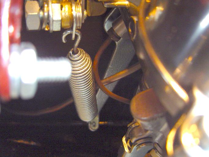
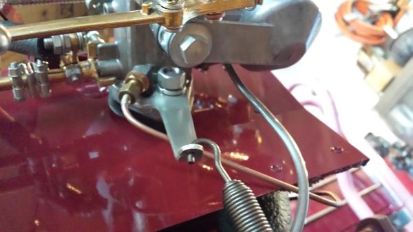
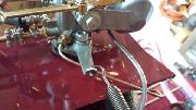
Two pipes in the picture above left are the vacuum line and fuel vent/overflow pipe. These would be better off running behind the spring bracket (like picture above right) leaving better access for wrenching on the lower carb mounting nut. Photo at left shows the later style male threaded nut when the adapter fitting was deleted (most MGA are like this). Photo at right shows the early style connector adapter with soldered end fitting and female threaded flare nut. You may have difficulty finding the early style vacuum pipe as a modern replacement part. The fittings are not interchangeable, because threads in the throttle body are different.
The distributor end of the pipe originally has a female threaded nut and another compression olive. If the distributor drive gear is installed properly, the vacuum unit will point straight up. The pipe connection nut will be underneath the heater valve, requiring a 90 degree turn in the pipe just above the nut. Life will be easier if you leave 1/4" of straight pipe above the nut. Pipe between the vac unit and P-clip on rear head stud has to flex when you rotate the dizzy for spark timing.
More photos from Ron Bissland in Kenosha, WI, USA
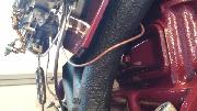
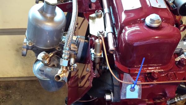
I would not attempt to wrap the vac pipe around the rear exhaust runner as shown here. Run the pipe downward from the fuel separator between the center and rear branches of the exhaust manifold, under the heat shield, and back up to the carburetor vac port. Form the pipe close to the heat shield to stay away from your wrench access.
|