The MGA With An Attitude
IGNITION COIL Function and Testing - IG-108
Maybe you don't really need to know how an ignition coil works to test it, but it helps. I will try to keep the explanation in layman's terms for simplicity.
  HOW IT WORKS:
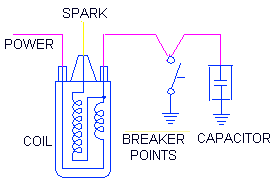
The ignition circuit on the MGA is quite simple. One primary terminal on the coil gets system power, and the other terminal is connected in series with a capacitor to ground return in the distributor. Additionally the contact points in the distributor parallel the capacitor to complete the ground return when the points are closed.
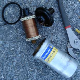 The ignition coil is a transformer with about 100 to 1 ratio between secondary and primary windings. The output voltage will be 100 times greater than the input voltage. Picture here is for reference only. You should never need to open a sealed ignition coil. If it doesn't work it must be replaced.
You can think of the capacitor as a small high speed storage battery. It can build up a positive charge on one side and negative charge on the other side. When polarity is suddenly reversed current will flow out of one side and into the other side. No current flows completely through the capacitor, but the current going in one side equals the current coming out the other side for the short time when it is charging or discharging. Meanwhile it simply stores a small electrical charge temporarily. The amount of power stored there is proportional to the voltage and frequency.
When the contact points are closed the primary winding of the transformer is connected in series with the battery and carries an electrical current of about 4 amps. Since the points are shorting across the capacitor, the capacitor does nothing (at that time). The core of the transformer is an electromagnet with magnetic field induced by the current flowing in the primary winding.
When the points open to break the ground contact the primary current must stop flowing, and the magnetic field in the transformer will collapse. The collapsing magnetic field forces current to continue flowing in the same direction momentarily, and that current will charge up the capacitor.
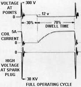 Forward inertia of this forced current raises voltage at the capacitor momentarily to about 300 volts, at which time this high voltage stops the current. The current then reverses direction, being driven backward by the high voltage at the capacitor. After the charge in the capacitor is depleted, inertia of the current in the transformer continues to drive the current in that direction to charge the capacitor in opposite polarity. The cycle then reverses. The result is an electrical ringing like a bell which reduces rapidly with time.
The initial 300 volt spike in the primary winding will drive an output in the secondary winding up to 30,000 volts. The output current going to the spark plug will likewise ring in harmony with the input current, for as long as the output voltage is high enough for current to jump the spark gap under compression. Assuming the initial spark ignites the fuel air mixture, combustion pressure will rise rapidly, and the spark will stop almost immediately as voltage falls. By now it should be obvious why the capacitor is an essential part of the ignition circuit, and the engine will not run without it.

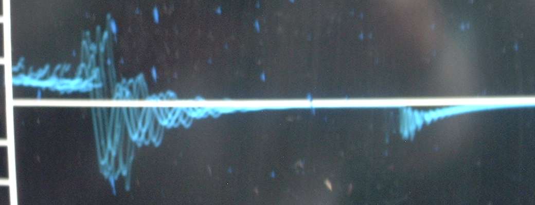
Picture from an oscilloscope showing multiple traces of sparks
For those following along with a little math, a four cylinder engine running 6000 RPM generates 200 sparks per second, so the full spark cycle lasts just 0.005 second. Dwell (time when points are closed) for the standard Lucas distributor is 60 degrees out of each 90 degrees of rotation of the distributor shaft, so the points are open only one third of the time, or 0.00167 seconds. How fast can you say "RING"? The only way you can ever see or measure this ringing, as in the picture above, is with an oscilloscope.
HOW TO TEST IT:
For preliminary test, use an ohm meter to check the resistance of the windings of the coil. For a non-ballasted ignition system like the MGA, coil primary resistance should be about 3.2 ohms. A high energy coil may have slightly lower primary resistance. A coil for use with a ballasted type ignition system (such as late model MGB) will have about half as much primary resistance, around 1.6 ohms. Resistance for the secondary winding will be very high, something like 7,500 to 10,000 ohms. Check that circuit resistance between the HT output and one of the primary input terminals.
To test the ignition coil function you will need a battery, a few wires, and a capacitor (about 0.01 mF value). Connect battery power to the coil. Mount the capacitor physically to a grounding point (return to battery opposite the power terminal), and connect the capacitor wire to the other side of the coil (terminal opposite the power input terminal). Connect a jumper wire to the coil along with the capacitor connection.
Touch jumper wire to ground (the capacitor mounting point) to complete the coil primary circuit. When you disconnect the jumper from ground, and you should get a nice spark from the coil. Touch jumper to ground, then pull away to make spark. Hold the coil output high tension wire near a grounding point to see how far the spark jumps. Spark should jump more than 1/4 inch in open air.
With all parts in place in the car, you can do this test with a single jumper wire. Leave all wires in the car connected. Remove distributor cap, and rotate engine until the contact points are open. This leaves the grounded capacitor in series with the coil. Turn on the ignition switch. Short the off side coil terminal (the one not connected to ignition switch power) to ground with the jumper wire. When you disconnect the jumper wire you should get the spark. This of course assumes that the primary wires inside the distributor are properly connected and are not shorted to ground. As a point of clarification, the two wires connected to the contact points must be in contact with the spring arm of the points and must not be touching the mounting screw.
If you do not connect the capacitor the spark may be so small as to be hardly visible, and lucky if it will jump 1/32 inch gap. The capacitor is an essential part of the circuit, providing an electrical "ringing" in the primary side of the coil at up to 300 volts. Without the capacitor the spark voltage would be reduced dramatically. If you get no spark from the coil, you need a new coil (or a new capacitor). If you get good spark from the coil, you know your problem lies elsewhere.
|