The MGA With An Attitude
MGA HEATER, AIR SWITCH Repair - HR-102A
All photos here are courtesy of Giovanni Delicio in Obrigheim/Pfalz, Germany.
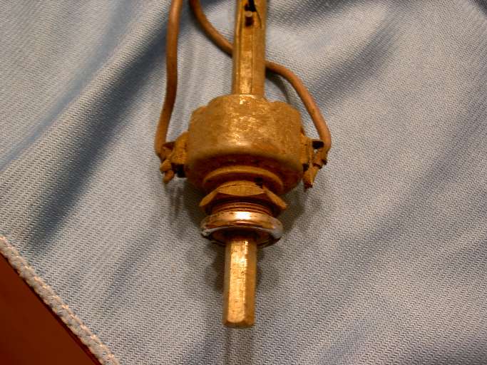
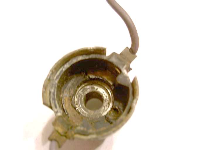
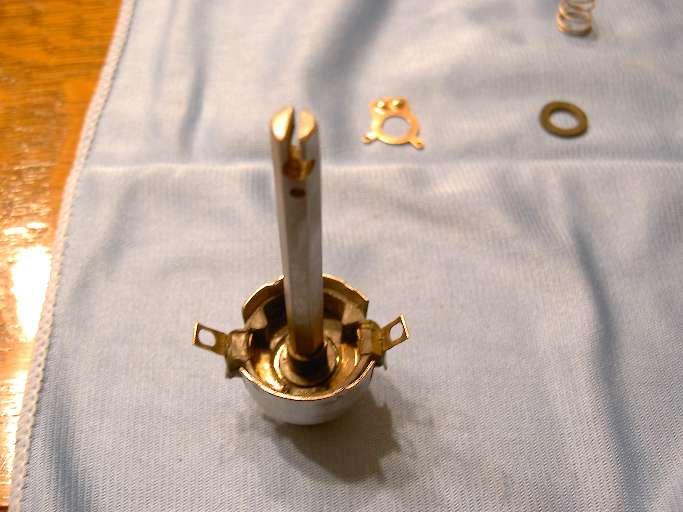
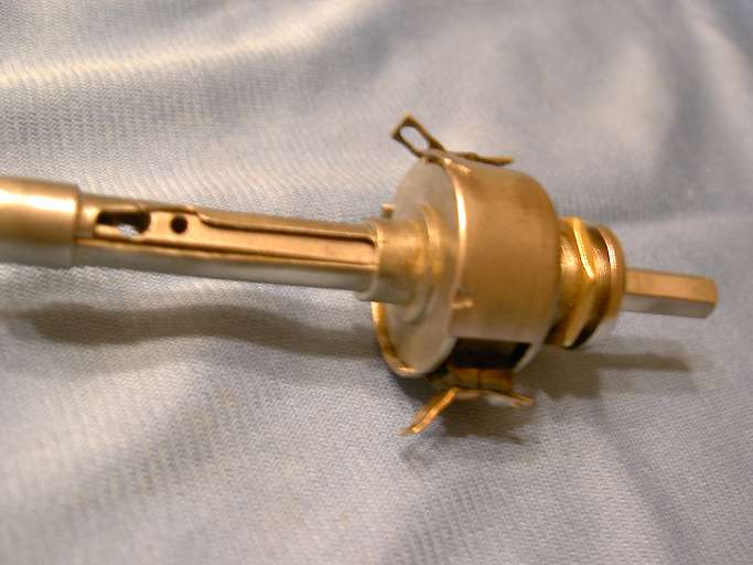
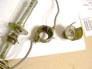
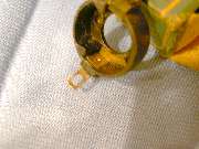
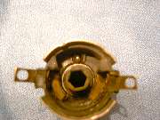
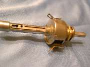
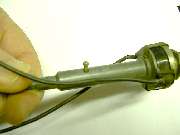
 This article is about repair of the early production MGA heater air switch with the "push and turn" function. I will start with a picture at right from the prior page showing the switch as removed from the car and with the knob removed. This one works mechanically but does not make the electrical connection when turned. Click for larger pictures.
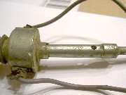
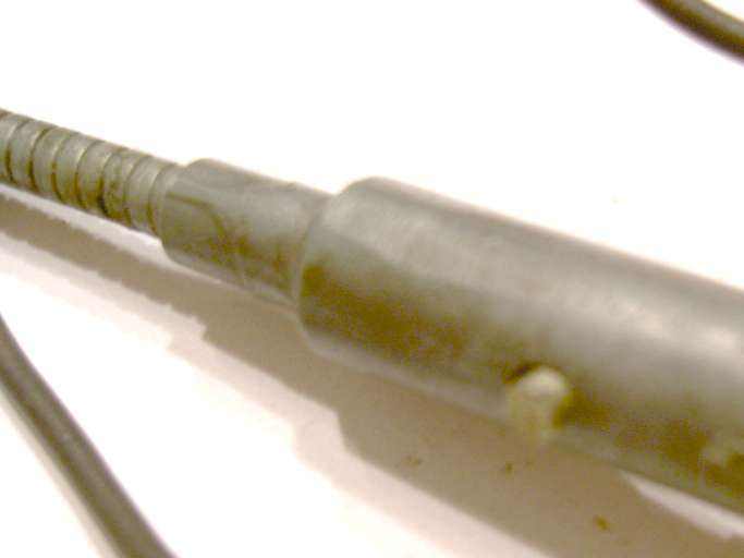
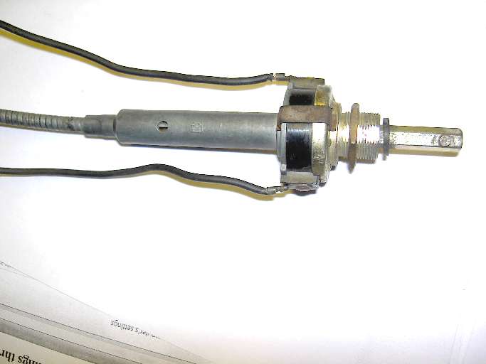
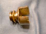
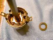
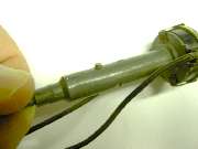
Starting with the rear housing, notice that the housing is swaged smaller at the end to secure the cable outer jacket for permanent assembly. You might be able to pull the cable jacket out of the housing (with enough force and a twist), but probably not able to push it back in. So if the cable jacket gets damaged, you would have to replace the whole switch assembly (which is not currently available new).
A quick side note here. Giovanni has successfully removed and re-installed the cable jacket. His description is. "I made a special gripper with a 'half-moon insert' and pressed back the crimps. [then crimped it back together] with a stub point chisel".
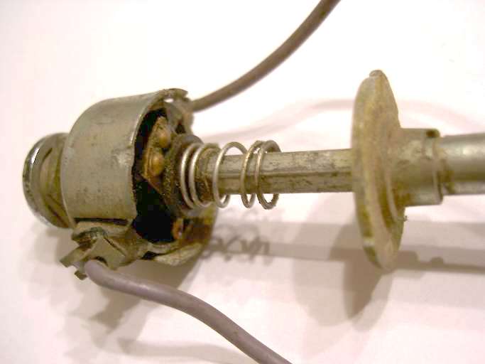
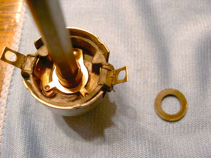
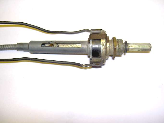
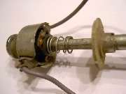
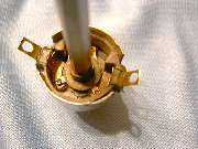
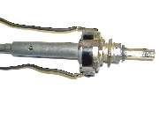
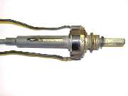
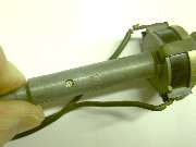
The rear housing of this switch has three pieces soldered together, a flat plate with two ears and a center hub (all one piece), a long tube, and a rear cap with stepped down diameter. You need to un-crimp four staked indents on the outer shell to separate the front and rear housings. This reveals the steel hex drive shaft, a compression spring and a couple of nylon isolator parts carrying a copper contact plate. The wire connections are "U" shape copper strips riveted in place with a hole in one end cradled around the wire insulation as a strain relief, and the wire soldered to the other end.
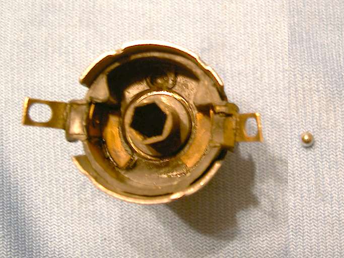
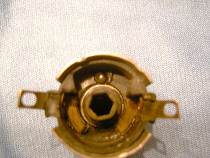
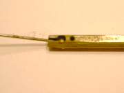
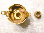
Looking at the shaft from the front you can see the contact plate cradled between two bits of nylon to isolate the contact from the shaft. Looking into the open front housing you can see a molded nylon inner shell (electrical isolator) carrying two arc shape copper contact strips that are riveted at the sides (for connection to the wires). There is a little round pocket at one side that holds a small steel ball to serve as a detent. There are also two triangular shape ears inside to serve as mechanical stops for the contact plate (which will rotate through a small angle). The contact plate has two spherical indents that will engage the steel ball at the two switch positions (rotate for on-off). You see the shell more clearly when it is removed from the steel front housing. The steel shell has large notches in each side for passage of the nylon carrier ears and electrical contacts to the outside.
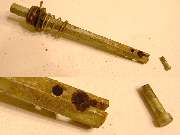
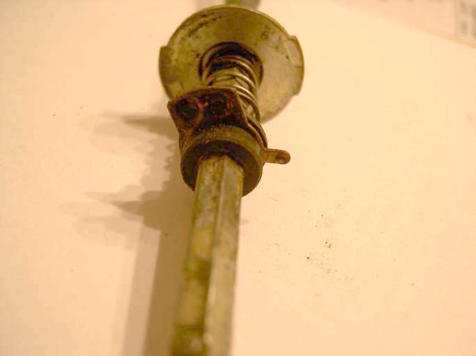
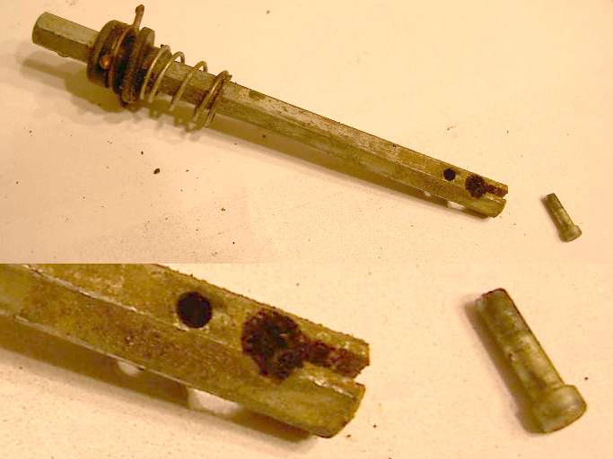
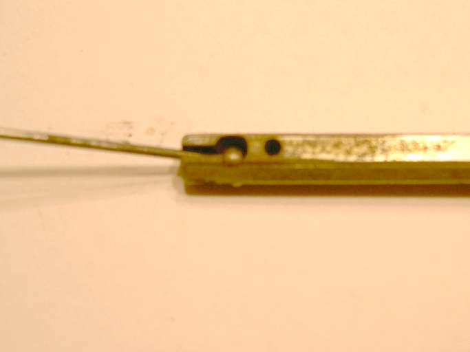
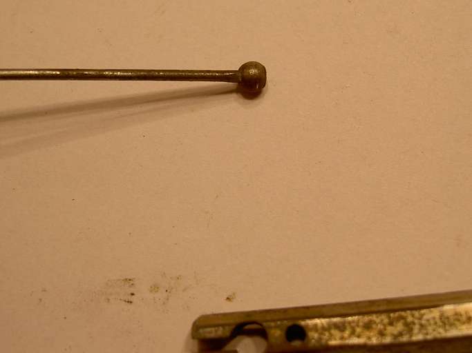
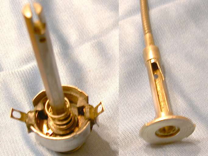
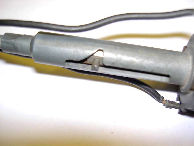
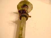
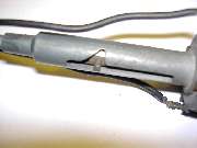
To remove the hex shaft from the rear housing you need to push out a cross pin that is a press fit in the shaft, then pull the shaft forward. Small end of the cross pin is in the guide slot. Larger head end of the pin is nested flush in a counterbore in the hex shaft, sliding inside of the rear housing. You need to align the head of the cross pin with the small clearance hole opposite side from the slot, then push or tap the free end of the pin to drive it out through the small access hole. When the pin is out you can pull the hex shaft forward clear of the rear housing. Once the shaft is out of the housing it can be disconnected from the inner cable. The inner cable has a spherical ball end that nests in a keyhole shape cross slot in the shaft. This allows the shaft to turn without twisting the cable.
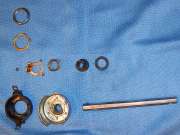
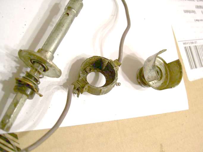
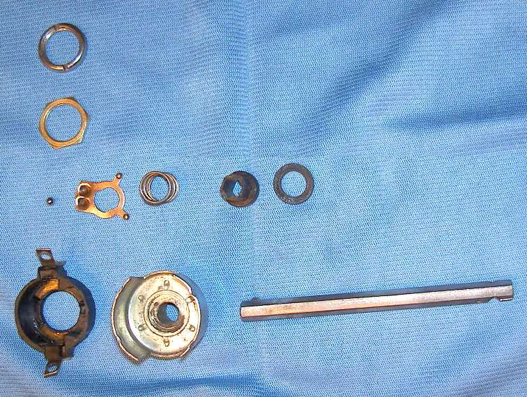
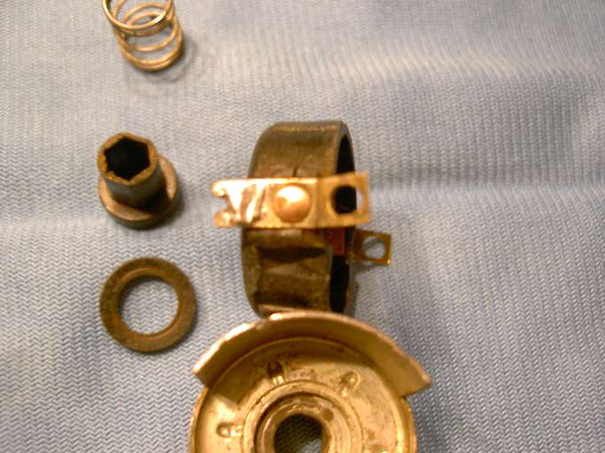
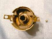
Once disassembled we can see all of the parts separately, in the picture with blue background. Upper left corner has two panel nuts that will accommodate different thickness panels as well as adjust for extension in front of of the panel. Then from left to right, the detent ball, the copper contact plate with double-D center hole, the compression spring, a nylon isolator with double-D outside and hex drive hole inside, and a nylon washer as isolator on the opposite side of the contact plate. At bottom left there is the nylon shell carrying the two crescent copper contacts inside, wire connections outside, and rivets to make the electrical connections from inside to outside. Then there is the steel front housing and the hex drive shaft.
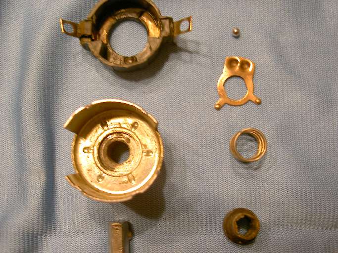
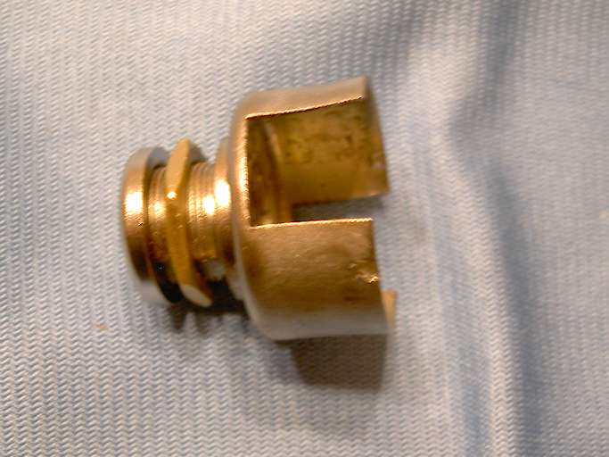
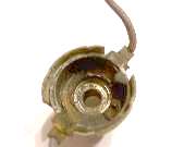
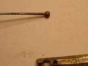
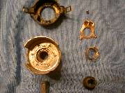
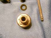
Next picture above is a close up of the smaller parts. Inside the steel front shell you can see six radial punched slots. These are staking points to displace metal for locking the stamped steel shell to the machined front hub. Do NOT disassemble this joint. The following picture shows front side of the steel shell revealing protrusion of the staking points. There is also the "D" flat on the threaded extension of the hub at upper left, 10:30 o'clock position (hard to see in the picture). You can also see the spring loaded pin on the hex shaft that will secure the plastic knob.
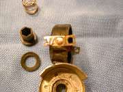
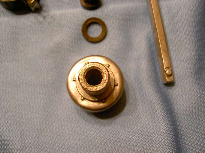
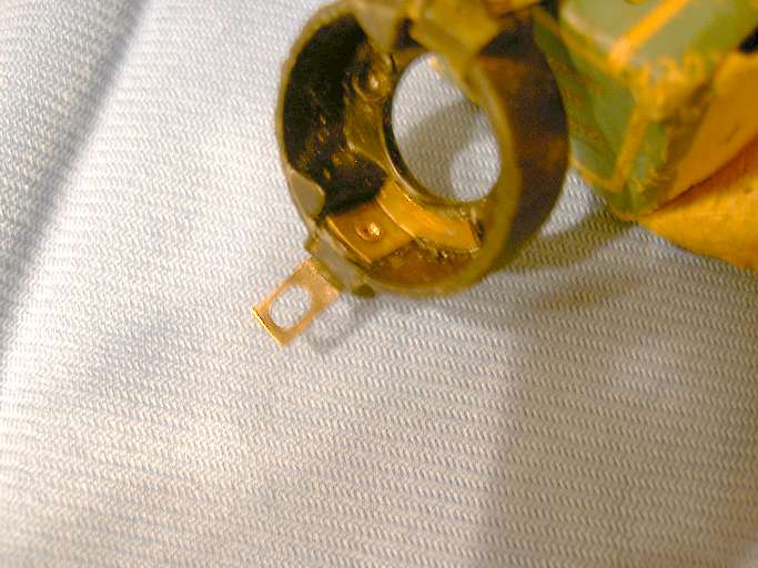
In the next two pictures you can see the rivet connecting the outside wire terminal to the inside crescent contact. This particular switch failure involved a loose rivet making a high resistance electrical joint and ultimately an open circuit, and allowing the outside terminal to rotate on the rivet. Pinching the rivet once again tight and cleaning the internal electrical contacts will restore proper operation of this switch. If you have trouble resetting this rivet, you might replace it with a small machine screw and nut. Last picture above shows the front housing with the two panel nuts installed. Here you can clearly see the "D" flat on the bottom side of the threaded hub. This is where we begin reassembly of the switch.
Start by dropping the nylon contact carrier into the front shell. Then insert the hex drive double-D isolator, and the little steel detent ball (all shown above).
Next insert the hex shaft, the copper moving contact plate, and the nylon isolator washer. At this point you need to pay attention to position of the front spring pin on the shaft in relation to the "D" flat on the the front threaded hub. Remember the spring pin holding the phenolic knob goes at bottom with final installation in the panel, and the "D flat on the front thread also goes at the bottom. The nylon contact carrier and the moving copper contact plate can be re-oriented 180 degrees with no ill affect as long as the spherical detents in the copper plate rest on top of the little steel ball.

Install the compression spring and prepare to install the rear housing. Pull the inner cable wire forward to engage the wire ball end into the keyhole slot in the hex shaft. Then push the inner cable wire back into the rear housing followed by the hex shaft. Push the front and rear housings together with rear housing ears engaged into side slots of the front housing. Orientation of the rear housing must be set to have the slot on top, as the hex shaft is polarized with the counter-bored hole that accepts the head of the cross pin. Stake the front housing rear edge over the rear housing plate in four places to secure the assembly. Finish by aligning the hole in the hex shaft with hole in the rear housing and installing the press fit cross pin (with tip of the pin in the slot of the rear housing). Also re-attach the connecting wires if they were detached.
Here are pictures of the second style switch, functionally same but probably cheaper to produce with a die-cast rear housing. The hex shaft has a counter-bored hole, so the cross pin goes in from one side only. The head of the cross pin seats flush in the counterbore on the shaft where it can slide inside of the housing, while the tip of the pin slides in the indexing slot. The rear housing is therefore keyed in a specific orientation to the shaft, so when the front spring button is down (along with the "D" flat on the thread being down) the rear slot has to be on top. By removing the two side clips the front shell can be rotated 180 degrees, so the "D flat on the front thread can be positioned at top or bottom. The nylon contact carrier could also be rotated 180 degrees during assembly with no ill affect, along with the mated rotating contact plate.
|