The MGA With An Attitude
HOW THE MG GEARBOX WORKS - GT-110
This dissertation was intended for an MGA, but most of it applies to the MG Midget and MGB as well, especially the early MGB 3-synchro gearbox, but not including any overdrive unit.
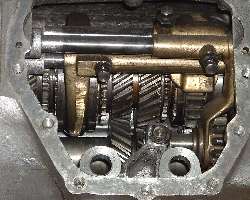 This is an explanation of the configuration and general principals of how the gearbox works. When you remove the side cover from the gearbox you will have the view shown here (but hopefully without the broken teeth on 3rd gear). Click for a larger picture, and you will want to keep this picture handy for discussion.
At the extreme left side of the picture (front of the gearbox) is the input gear. The input shaft is often called the "first motion shaft". The mainshaft has its nose being carried in a needle bearing in the center of the input gear, and extends all the way to the back end of the gearbox where it couples to the propshaft to drive the rear axle assembly. The mainshaft is often called output shaft or "third motion shaft". The laygear, at bottom in photo, is a cluster gear, all one piece, containing the input driven gear at front, followed by 3rd and 2nd driving gears in center, and a small spur gear at the rear (hidden at far lower right in this photo) to drive 1st and reverse gears. The laygear ("lays" in the bottom of the box) spins on needle bearings on the fixed layshaft. This assembly may be called "second motion shaft". It follows that 1st motion (input) drives 2nd motion (laygear) which in turn drives 3rd motion (output).
The input gear will be turning clockwise any time the engine is running and the clutch is engaged. The lay gear is driven anti-clockwise. With neutral selected, 2nd and 3rd gears freewheel (clockwise) on bronze bushings on the mainshaft. You should notice that the helical gear teeth for 2nd and 3rd gears are always in mesh with the laygear. On the sides of the input gear and 3rd gear and 2nd gear are small teeth which can connect to a female spline in the adjacent sliding hub on the mainshaft. Moving the sliding hub into engagement with these small teeth will lock the gear to the mainshaft to drive the output. There are synchronizers (function to be discussed elsewhere) between these gears and the sliding hubs. Therefore this type of unit is called a "synchromesh gearbox".
First gear is the large spur gear at right in the picture. This is keyed to the mainshaft (in a gearbox with a non-synchronized 1st gear) and will always rotate in unison with the output shaft, clockwise for forward drive, anti-clockwise for reverse drive. First gear is also the outer moving part of the sliding hub. The medium size spur gear in the lower right corner is reverse gear. This is actually a pair of gears, all one piece, with the slightly larger spur gear on the right (almost completely hidden in the picture), and it rotates on a separate short fixed shaft. With neutral selected, reverse gear is not engaged and can remain motionless.
At top of picture are three shift rods. To each is attached a bronze shifting fork. The rods and forks are moved fore or aft, one at a time, to select (engage) various gears. Reverse and 1st gear engagement happen at the rear of the box, followed by 2nd and 3rd in the center, and 4th at the front. The top shift rod selects 1st or 2nd gear. The bottom shift rod selects 3rd or 4th gear. The middle shift rod selects reverse gear.
When shifting into 1st gear the large spur gear is moved rearward to engage with the small spur gear on the layshaft. Just coincidentally, it will also engage with reverse gear at the same time, so the reverse gear pair will be freewheeling when 1st gear is in operation. If you want to be nice to your gearbox, you shift into these non-synchronized 1st or reverse gears only when everything is motionless, so you don't grate or grind the gears and chip little fragments off of the corners of the teeth on the spur gears.
When shifting into 2nd gear, the sliding hub (including 1st gear) is moved forward to lock 2nd gear to the output shaft. When shifting into 3rd gear the forward sliding hub is moved rearward to lock 3rd gear to the output shaft. When shifting into 4th gear the sliding hub is moved forward to lock the input gear to the output shaft. In 4th gear the input and output shafts turn together as one, while 2nd and 3rd gears are still freewheeling on the mainshaft.
To shift into reverse, the reverse gear is moved forward. This engages the smaller reverse gear wheel with the 1st gear wheel on the mainshaft, and at the same time engages the larger reverse gear wheel with the small spur gear on the laygear. Connecting this reverse idler gear in between the laygear and 1st gear ring reverses direction of rotation of the output shaft.
There are large ball bearings in the front and rear of the main housing. Aft of the main housing, inside of the tail housing, are the speedometer drive gears and mainshaft rear support bearing, and also parts to generate some oil flow to lubricate the bushings and bearings. Operation of synchronizers and gearbox lubrication are discussed in other articles.
Inside of the front bellhousing are the clutch parts. The clutch friction disk and pressure plate are mounted on the engine flywheel. The clutch release arm and release bearing are mounted on a pivot bolt attached to the gearbox front cover. A hydraulic slave cylinder is attached to the lower outside of the bellhousing to operate the clutch release lever. The nose of the gearbox input shaft (called the "spigot") is carried in a small bronze bushing (the spigot bushing) located in the tail end of the engine crankshaft. Any time the engine is separated from the gearbox it is advisable to inspect the spigot bushing and replace it if necessary. If the spigot bushing is worn it can have some bad effects, generating vibration and noise during clutch operation. It is a really cheap part, but otherwise difficult for access.
If your gearbox front cover is an original MGA 1500 or 1600 part, it won't have a rubber seal. But it is common practice to fit a front cover from a later 1600 MK-II gearbox which has a rubber seal. The early MGB front cover will fit on the MGA gearbox, but it has the pivot point for the clutch throw out arm in a different location to accommodate the thinner MGB clutch pressure plate. This cover uses the same seal as the late MGA part. Any cover with the seal and the seal itself will work with your original input shaft.
Now you may remember that little split pin in the bottom of the bell housing. This is a functional part (surprise). A bit of vibration with the split pin keeps the drain hole clear of dirt to prevent clogging. There are gaskets for the front cover, side cover, front housing to rear housing joint, shift selector cover, and two more for the remote control tower. Also a plastic washer at the speedometer drive fitting, and a felt seal on the oil dipstick (maybe not available separately). There is also a rear seal, a seal on the speedometer drive pinion shaft, and a large rubber gearbox mount in the bottom of the tail housing. Find pictures and descriptions of various gearbox models in GT-101
|
