The MGA With An Attitude
TUNNEL MODIFICATION, On Top Of Floor - FR-205
In original assembly the MGA tunnel (gearbox cover) is installed on the frame prior to installation of the floor boards. Therefore the floor sits on top of the tunnel flanges. Before proceeding with the rest of this article, please review FR-109, "Installing the MGA Center Tunnel".
For removing the engine and gearbox, the Workshop Manual refers to removing seats, carpet, floorboards and tunnel, then removing engine and gearbox together. (I'm glad no one told me that before I pulled the engine when I was 20 years old). That scenario is only necessary on very early production cars that did not have the separate tunnel top cover (item 10 in illustration). Otherwise you can remove the center carpet section only and the tunnel top cover. Follow this by removing the gearbox remote shift extension (4 bolts), after which the gearbox can be pulled out the front through the engine bay (with the engine or after removal of the engine).
That said, a MGA Twin Cam engine requires significantly more work to R&R than the standard pushrod engine. Some racing enthusiasts who run a car with minimal interior would also like to be able to R&R the gearbox without having to remove the engine. As such, a few select people will take the time to modify the tunnel to have the flanges sitting on top of the floor rather than underneath, allowing R&R of the tunnel and gearbox without removing seats and floor.
First order of business in this modification is to remove seats, carpet, floorboards, and tunnel. If you do not remove the propshaft you will need to remove the internal reinforcement plates around the hand brake lever mount. That would effectively dismount the hand brake lever assembly, leaving the inboard arm and cable attached. Reinstall the floorboards temporarily with only a few screws. Then set the tunnel parts back in place on top of the floor.
At this time you would notice that the tunnel sits about 1/2 inch higher than before. This includes the rubber boot around the shift lever, the hand brake lever, and multiple bolt holes in the tunnel front and rear flanges. Some people will then drill new holes in the bulkhead boards and frame, followed by installing some new captive nuts. In the interest of quickest R&R of the tunnel it is preferable to provide for ALL of the tunnel flange assembly nuts to be captive in the chassis. This may require adding a small frame brace under the inboard edge of the heel boards to support that edge of the board and to hold a few captive nuts. Also remove a couple of captive nuts from the bottom of the tunnel flange. You might otherwise install all floorboards first with all screws in place. Then drill small holes in the tunnel flanges and use wood screws to attach the tunnel to the floor boards.
You should also notice that the front tunnel section will sit nearly 1/2 inch farther back after it is placed on top of (or aft of) the toe boards. This almost certainly requires cutting off the front flange and moving it back 1/2 inch. You can cut about 1/2 inch aft of the front flange, then overlap the metal to move the flange back 1/2 inch, and weld it back together. When doing this, there is a length of the flange that attaches to the bulkhead plate above the toe boards. This part of the flange should either be left in original position or reattached in original position after cutting. You need a total seal here so that engine compartment fumes will not enter the passenger compartment.
There may also be an issue with the internal tunnel brace plates (item 12 in the illustration above) being too close to the propshaft. Notice also where the tunnel sits above the rectangular frame cross member (between seat board and heel board). Here there will be a gap where there was originally a weather seal. It would be appropriate to weld in a small piece of sheet metal here to close the gap.
One side benefit of this setup is that you may not need to remove the tunnel top cover (at the shift lever) when removing the tunnel. In the end the gearshift rubber boot would be 1/2 inch higher, which may be no problem. The rubber plug above the gearbox dipstick will also be 1/2 inch higher, which can make it even more difficult to R&R the dipstick for checking gearbox oil level (consider adding an extension to the dipstick handle). Of course the car will no longer pass concours show inspection.
Rather than raising the tunnel 1/2 inch, it is a slick trick to only raise the bottom flanges. To do this you can cut horizontally down both sides of the tunnel about 1/2 inch above the bottom flanges. Then you can overlap the sheet metal and weld it back together with the flanges 1/2 inch higher. This leaves the tunnel at original height and avoids any modification of front and rear flange attachment bolts. For concours enthusiasts, you might consider removing a 1/2 inch wide ribbon of metal on both sides followed by butt welding the parts back together and grinding smooth to hide the welds (rather than lap welding). This also makes it more weather tight to keep out water splash intrusion (or oil stains on the carpet).
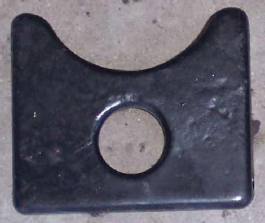
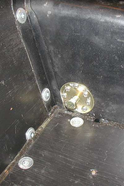
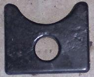
When cutting and relocating the bottom flanges there is a tactical problem with the hand brake lever mount. The four-bolt plate is originally attached so low that the bottom two bolts are nestled in along the edge of the floor board, and the board is notched for clearance (visible on item 1 in illustration above). When the tunnel is not raised, and the tunnel inner braces are not raised, it may be necessary to also leave the hand brake mount at original height. This might require some additional creative flanging and weather sealing around the bottom edge of the hand brake mount.

There is also a safety concern here. If the car has seat belts attached to the lower rear corner of the tunnel (late factory specification), then you should be concerned about having the rear tunnel section very securely attached to the FRAME, not just loosely screwed to the floor boards. The good news here is that the tunnel rear section may not need to be removed to R&R the gearbox.
One more probelm remains for removing the gearbox from inside the car. Apparently the top flange of the bellhousing holding the top two bolts is hiding somewhat in front of the lower bulkhead plate. While these two bolts can be removed from in the engine bay, the bulkhead plate may be in the way of moving the gearbox rearward for removal. This then would require removal of the bulhead plate, which in turn would require removal of the steering column that runs through that plate. ONe person split the vertical panel at the hole for the column and welded on a narrow overlap strip to disguise the cut. This enables removal of the long section of the panel without disturbing the steering column. A couple other people report making a pair of vertical saw cuts and bending up part of this panel rather then removing it, then bending it back down during reassembly. That sounds like a botch job to me, and the panel might crank after the first or second operation, so I would definitely not recommend cut and bend.
|