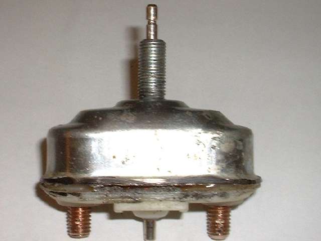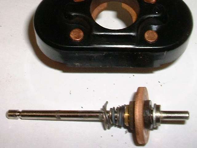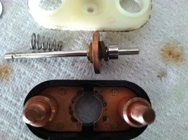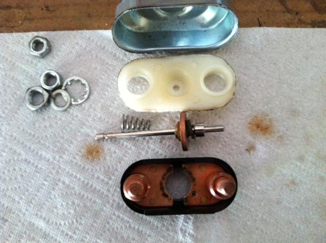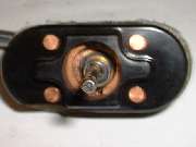
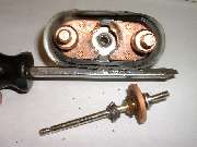
Upon removal of the outer shell, inspection into the front of the device (second picture above) reveals that the return spring is discolored, collapsed, and broken into multiple pieces. This is obviously the result of the spring having carried a high electrical current, causing it to heat to high temperature so as to lose the spring temper. In normal assembly this spring would extend from the moving parts on the pull rod to the inside front of the metal case, and would be in compression when at rest. This spring provides force to keep the moving plunger seated in the rearward position when at rest, the resistance to pull on the spindle, and also the force to return the draw cable and dash mounted pull knob when released. This spring will be electrically grounded to the case inside at the front, so the next question is how it came into electrical contact with the normal power carrying parts, which it should never touch.
As a matter of curiosity (but of no consequence here) the slight melting at the edges of the nylon base plate was a result heat from grinding on the case flange during opening of the unit. The part broken side of the phenol-fiber inner shell was a result of twisting with a heavy pliers when removing the outer shell. None of this has anything to do with the function or failure of the switch.
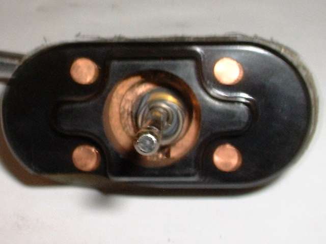
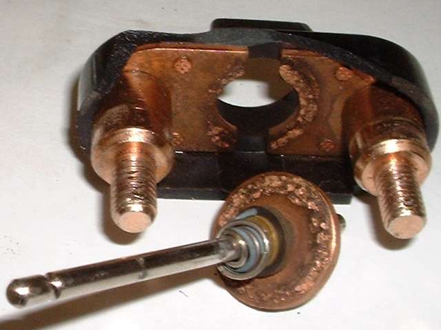
In the last picture above, the discoloration and speckle marks on the copper disk and on the primary contacts inside of the phenolic case is a result of normal operation of the switch and some arcing when the heavy current contact is made between these parts. This has nothing to do with the failure of the switch. Since none of the moving parts on the center spindle other than the copper disk could have come into contact with the fixed heavy contacts in the phenolic case, attention must turn to the relationship of the copper disk to the rest of the moving parts.
In operation the heavy copper disk must remain at all times electrically isolated from the central pull rod and spring (or springs), such that the disk will only find electrical connection with the two fixed contact bars in the phenolic case. Inspection of the moving parts reveals that the copper disk is mounted on a central fiber insulating ring and flanked by two flat fiber washers, which should electrically insulate it from the central spindle and from all other surrounding parts. The key word there is "should".
In front of the forward fiber washer is what first appears to be a thin brass washer with close fit on the shaft. This is in fact the forward flanged end of an eyelet, or tubular rivet. This eyelet has a close sliding fit on the shaft, and is about three times as long as the shaft diameter, therefore allowing it to slide on the shaft without cocking or binding. A small snap ring in front of the eyelet fits into a groove in the shaft, effectively retaining the fiber insulator and copper disc assembly and preventing these parts from moving forward on the shaft. Behind the insulator assembly there is a flat steel washer with a close fit on the shaft, and behind that a rigid shoulder on the shaft which is an integral part of the shaft. These parts will prevent the insulator and copper disk assembly from moving any farther back on the shaft. So with these parts in place, when the shaft moves fore and aft the electrically isolated copper disk will move with it.
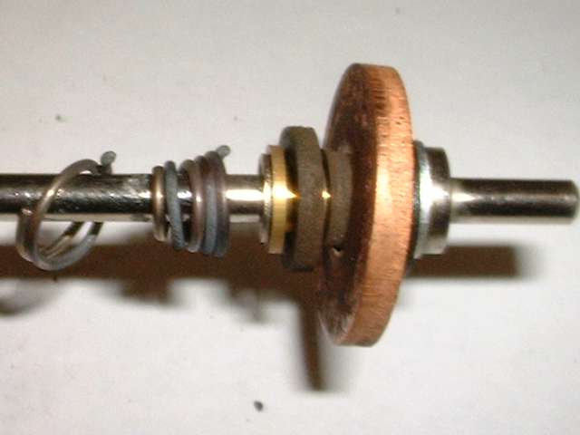
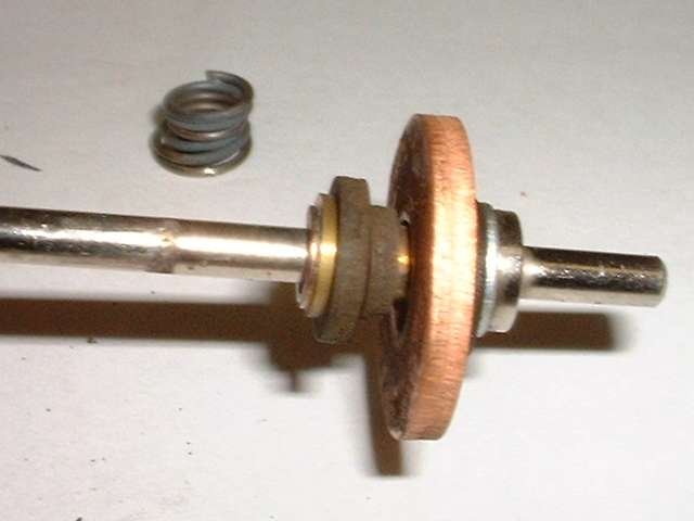
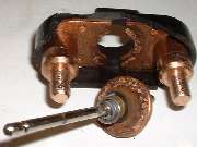
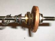
Now turn your attention to another small coil spring immediately in front of the steel washer but behind the fiber insulator assembly, best visible in the picture at far right above. This appears to be in the wrong place. I believe it should be positioned in between the steel washer and the flange on the shaft, such that it would hold the steel washer firmly against the insulator assembly, which would in turn keep the flat fiber washers in intimate contact with the copper disk, at all times, and the insulator assembly also pressed forward against the front flange of the brass eyelet. All of the parts from the small brass eyelet back to the small steel washer would then be free to move fore and aft in different circumstances while always remaining forcibly sandwiched together by the springs on either side.
The spring at the back has a smaller diameter coil than the front spring, as well as being shorter with fewer coils. This gives the rear spring a higher force and higher spring rate than the front one. Throughout most of the pull stroke of this switch, the rear spring would remain extended, holding the insulator assembly in the original forward position on the rod, pressed firmly against the snap ring in front. When the large copper disk comes into contact with the fixed copper bars, the copper disk must cease forward motion. If (when) the operator continues to pull the switch actuator knob and cable farther forward, the rear spring would compress with some force, giving a firm dampening feel to the pull knob, similar to a shock absorber at the front end of full stroke. This rear spring will then also hold the heavy copper disk in firm contact with the fixed copper bars to retain a good electrical power contact, even if the operator should happen to twitch a bit with the pull knob.
At the same time when the copper disk stops and the pull rod continues forward, the eyelet will slide on the rod leaving a bit of space between the eyelet forward flange and the snap ring. The forward spring might be in direct contact with the flange on the eyelet, or it may be in contact with the snap ring. The only difference there is whether the forward spring is pushing the eyelet back on the shaft, or if the eyelet is being dragged back by the motion of the large copper disk and fiber insulator assembly. Because the forward spring is so badly deteriorated, it is difficult to tell for sure without having a good one in hand, but it appears that this spring should be resting against the snap ring and not pressing directly on the eyelet. This means that the front spring will not upset the position of the rear spring. while the plunger is in motion, and only the physical contact of the large copper disk with the copper bars will cause compression of the rear spring.
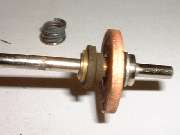
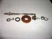
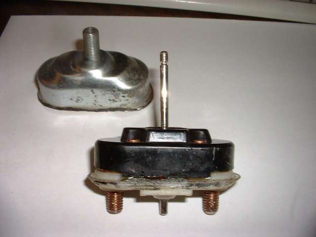
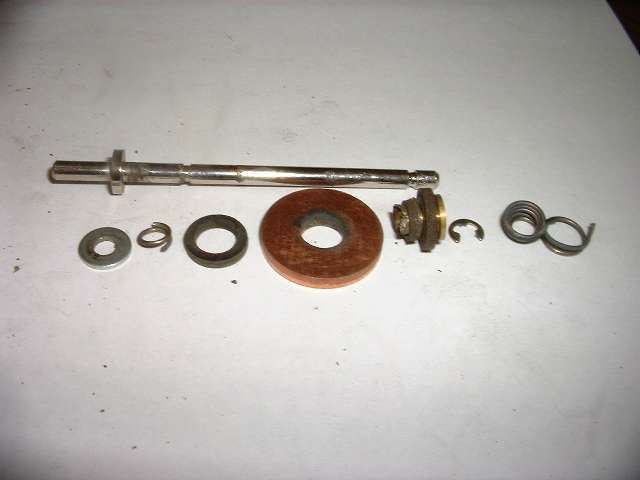
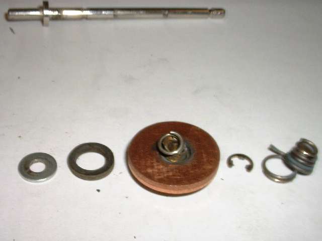
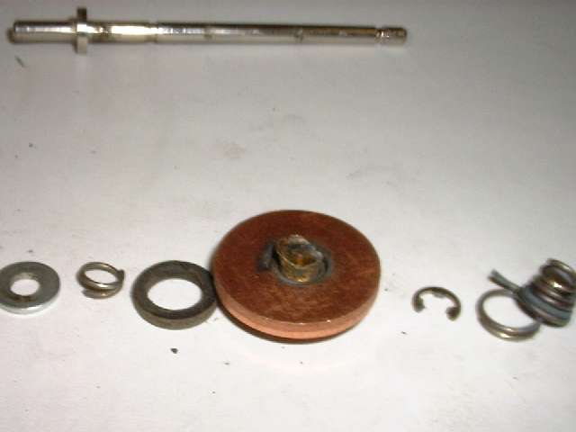
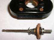
Now that we understand how the switch is supposed to work, we still need to find out what went wrong. Looking at the first picture above left, we can see that with a small nudge the large copper ring can fall off of the inner insulating ring and into contact with the eyelet. This of course should never happen, and we need to determine why the rear spring is not holding this assembly together. So now it's time to remove the snap ring and disassemble the parts from the shaft. From here on the parts are pictured with the reward parts to the left and forward parts to the right. The first picture above with loose parts (second picture from the left) shows the parts in the same sequence as they were removed from the spindle.
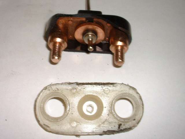
Notice that the rear fiber washer has a large inside diameter, almost equal to the ID of the copper ring (but not quite). The copper ring does fit over the small central fiber ring, but the rear fiber washer does no quite fit over the small fiber ring. This appears to be a second error in the assembly, in that the rear fiber washer should probably be the same type part as the front fiber washer, and should be a close fit on the brass eyelet. In fact the rear fiber washer should probably be crimped onto the eyelet such that the large copper ring would not be removable from the fiber insulating assembly.
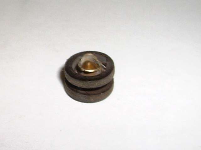
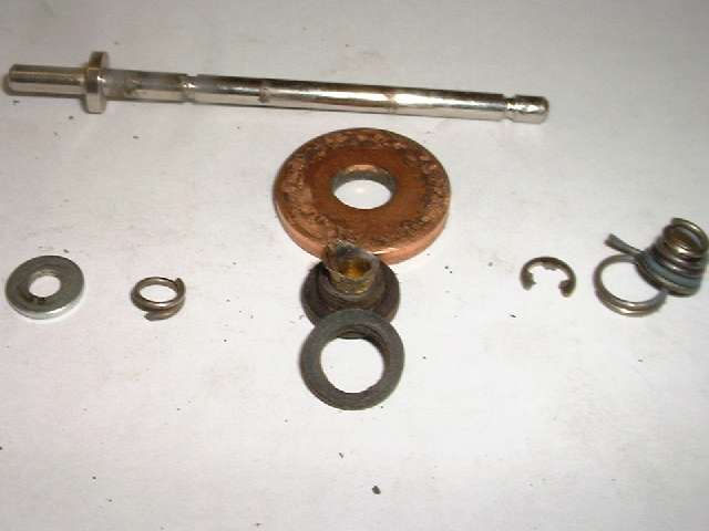
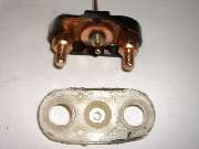
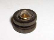
As another test the eyelet is placed with front end down, and the rear fiber washer is placed on the assembly as it would be inside the switch. See third picture above. Here the eyelet appears exactly the right length to be crimped tightly on the rear fiber washer, if only the ID of this washer were small enough to fit the shank of the eyelet. But instead the eyelet has a bell shape with split open end like it was peened into open air with nothing physical to bear against.
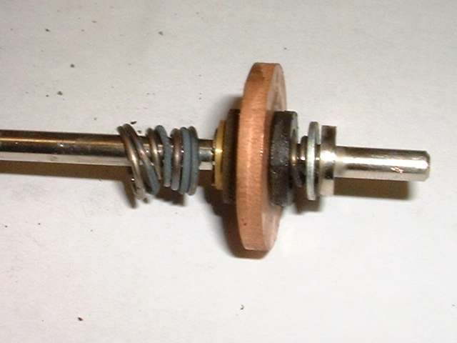
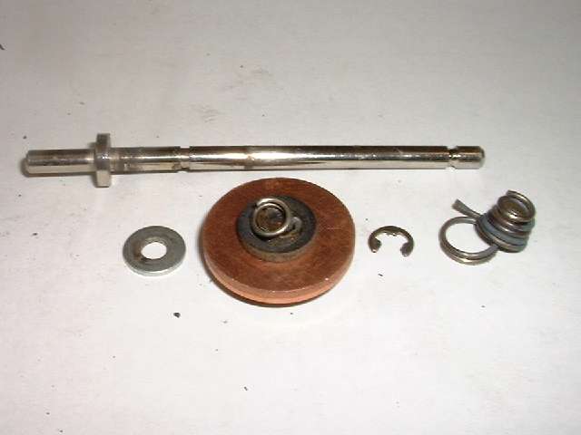
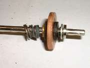
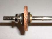
To further test the theory of the way this should be assembled, the last picture on the right above shows the parts reassembled with the rear spring behind the steel washer. This does indeed hold the insulator parts together to prevent the copper ring from contacting the spindle or the eyelet. Then when the copper ring is pushed firmly rearward on the spindle with some force, it has exactly the same firm spring feel as the good original equipment starter switch which is installed in my car (1958 MGA) when that switch hits end of travel. This is about as close as we get to verifying correct assembly order without dissecting another good original type switch (which I do not currently have in my possession anyway).
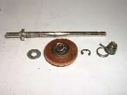
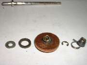
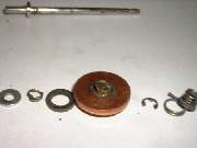

To review a few points for clarity, the first picture above left shows the fiber insulator parts stacked in the correct order with the copper ring. It also has the small rear spring in physical contact with the back end of the eyelet as it was before this faulty switch was opened. If these parts were moved slightly, the small spring could fall completely inside of the rear fiber washer. This is exactly what is shown happening in the first picture in second row up, where the copper ring is in contact with the eyelet. The second picture above shows the rear fiber washer removed, and the rear spring sitting on the eyelet. The third picture shows the spring removed and the ragged end of the eyelet exposed. The last picture above has the copper ring removed and the offending fiber washer leaning on the good fiber parts. Also recall in the right side of all of these pictures, the front spring which is distorted, discolored and broken from electrical heating.
So there appear to be a few things wrong with this switch contributing to it's failure. First is an incorrect part in the form of a fiber washer with oversized center hole. Second is a somewhat distorted eyelet resulting from bad peening as a result of the wrong fiber washer. Third is an incorrect assembly sequence where the rear spring was installed in front of the rear washer, having about the same effect as if the rear washer was left out of the assembly. The combination of the wrong rear fiber washer and the rear spring in the wrong position could allow the copper ring to come into contact with the eyelet on the pull rod. Then as this switch would be pulled in attempt to start he car, when the copper ring would contact the copper bars carrying battery power, an electrical contact could be made from the copper ring to the pull rod, and from there a high current could be passed to chassis ground in various ways.
Power could pass through the front spring to the metal case and on to chassis ground. Having a short circuit from battery to ground through the front spring, this spring would get very hot very quickly, soon fail from annealing and ultimately melting and/or breaking. While this switch is in the pulled position and making internal contact, a high current could also be passing through the shaft coupling and the pull cable to ground at the dashboard, or anywhere that the pull cable might happen to be touching anything else which is grounded. The set screw which holds the pull cable in the shaft coupling may provide a high resistance joint (or a frayed cable of reduced diameter) to cause more heating of the cable at that point, and possibly cause burn failure of the pull cable. And if the pull rod was in contact with the inside of the switch mounting bezel, that too could give another short circuit path to chassis ground. Sparks and smoke might emanate from the switch either because of the front spring burning and arcing, or from the pull rod shorting to the front case.
Conclusion is that this switch was manufactured with defects of an incorrect part, poor workmanship, and improper order of assembly. Under the circumstances, other switches produced in the same production run would also be suspect of possibly having similar defects. This defect can contribute to various hazards in the automotive installation, including possible fire or personal burn hazard and/or physical damage to related components in the vehicle, and damage to the vehicle battery possibly even explosion of the battery or expulsion of battery acid. As such, some effort should be made to notify the part manufacturer and any and all intermediate distribution and end sales entities as well as any final buyers. Consideration should be given to a possible recall of any of these switches which can be identified either out of remaining inventory or in the hands of end customers.
P.S.
Unfortunately this starter switch came with the purchase of a well used MGA, and the history or source of the switch is unknown. We only know that by design it is an aftermarket replacement type part, and it appeared to be fairly new, or at least little used. If anyone else should happen to have the same problem, and perchance might have some clue as to the origin of the part, do tell.
Addendum August 3, 2014:
We have had continuing regular reports of failure of this type switch (with the white nylon insulator) for more than 10 years. Some report shorting to ground. Others report high resistance of the contacts resulting in no current or reduced voltage to the starter motor. This time we have a report of the switch sticking in the engaged (closed contacts) position.
On 8/3/2014, Stephen Miller wrote:
"Voltage drop became the next problem, oh well".
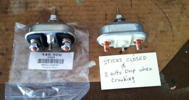
 "This is my switch that was sticking closed, and finally had serious voltage drop causing start problems. Took this one apart. What I found are two things that seem troublesome. "This is my switch that was sticking closed, and finally had serious voltage drop causing start problems. Took this one apart. What I found are two things that seem troublesome.


"First (as you can perhaps see in the photo) there is an insulating ring on the lower side of the disc and shaft which insulates the disc from the shaft. On this one, as I pulled on the disc (disassembled) the rubber insulator pulled away from the disc and left it loose. Seems to have been glued to the inner insulator. It will go back into place easily, but will not stay, and the disc is now loose from the shaft. Not sure how this was designed to withstand the forces of pulling against the disc and spring w/o pulling loose. If I were to redesign, I would add a thin washer between this insulator and the rear spring which would prevent pulling the disc loose from insulator. I will say that even after my use on the car, it was still intact, per se, and allowed the disc to move slightly to align to the base contacts.
"When I first looked at the disassembled device, I must say I was very impressed with the apparent quality of manufacture. There are clear signs of welding between the disc and the base contacts, which had me wondering, until I used a magnet to determine that both the disc and the base contacts are just steel, with a copper flashing. If I understand the old normal devices for handling these heavy current loads, both contact surfaces must be of copper, not steel".
On 8/9/2014, Steve Miller wrote:
"With a bit more looking at your article and pics, I see that there IS a washer between the small spring and the insulator, and that washer is missing from my assy. Guess the Chinese kids were having a bad day or two on some of these. But trying to shortcut and use steel for the contacts is bad juju".
|