The MGA With An Attitude
OIL FLOW PATH, MG B-Series Engines -- OF-101
This article explains the flow path for oil through the B-Series engine, and explains how everything in the engine gets oiled. This is a copy of my e-mail response to a question on the mgs list in October 1997.
On Sun, 19 Oct 97 14:45:32 -0400 Larry Macy <macy@bblmail.psycha.upenn.edu> writes:
>On 10/18/97 11:29 PM so and so Scott Gardner said. (And I quote)
>>.....Can anybody tell me the exact path the oil takes through a 18V engine? Please include the filter, oil pressure relief valve, and cooler in the path. I'd especially like to know where the oil pressure gauge sender is in the path as well.
>>Also, where does the oil go when the oil pressure relief valve opens? Is it possible for the main bearings to be completely starved of oil and still have pressure on the gauge? Somebody mentioned oil gallery plugs on the bottom of the engine. What are they, where are they located, how many are there, and what would the effects be if they were missing?<<.....
>In most engines the oil goes to the cam first and then through the gallery to the mains and then from there to the con rod bearings. Makes it easier to drill. the relief valve is on the way to the cam. If this is diff in the MG - 18V engine, somebody will say - Barney??<
 Yes, it is different in the MG B-series engines. As a supplement to this article, you should also see the following article OF-101A detailing the oil drilling holes in the engine block and cylinder head.
Oil is picked up from the sump via the oil strainer and riser tube, and passes through the pump and into the left rear corner of the engine block. There it encounters the pressure relief valve where excess oil is forced past the relief valve and returns directly to the sump. Oil not dumped by the relief valve passes into a cross drilling at the back of the block to emerge at the external pipe fitting at the right rear corner of the block.
If the engine does not have an oil cooler, the oil passes through an external steel pipe to the oil filter housing. If the engine does have an oil cooler, the oil passes through a hose (and maybe also a pipe) to the cooler, through the cooler, and back through another hose (and maybe a pipe) to the oil filter housing.
When the oil enters the filter housing it passes into the outer portion of the filter, then inwards through the filter to the central space, then back through the filter mount into the engine block. There is also a pressure relief valve in the filter mount (or in the filter itself in some cases) which will relieve itself if the filter gets dirty and clogged, and the oil which cannot pass through the filter element will bypass the filter element and enter the engine block directly without being filtered. If you change your oil and filter regularly this condition should never occur, and all the oil entering the engine block should be filtered.
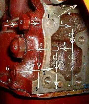
Once back in the block the oil enters a drill hole (oil gallery) running the length of the engine from front to back (right side of the block). At the front, a small hole allows a bit of oil to pass through the timing chain tensioner where it flows onto the timing chain before returning to the sump. Just a couple of inches from the back, a port is tapped from the gallery to the outside of the block where the flex line to the oil pressure gauge connects. In three places (five for later engines) there are drillings from the main bearing journals to the gallery, where oil flows from the gallery to the main bearings. So, the pressure gauge registers system pressure after the filter and just before the main bearings.
There are diagonal holes drilled in the crankshaft from the main bearing journals to the rod bearing journals, and oil flows here to get to the rod bearings.
There are more holes drilled in the block from the main bearing journals to the camshaft bearing journals (three places), so oil flows from the main bearing area to the cam bearings (three cam bearings in all engines, even those with 5 main bearings).
The drill hole supplying the center cam bearing is extended farther to merge into the low pressure oil gallery at left side of the engine block. The low pressure oil gallery drill hole extends full length of the block same as the high pressure gallery on the right side (also plugged at both ends). The low pressure side feeds oil rearward to oil the cam gear that drives the oil pump and distributor. And I believe the low pressure side will also supply oil to the tach drive gear at the rear end of the camshaft.
There is also one vertical hole from the rear camshaft bearing journal where oil can flow upwards to the top of the block. The camshaft rear journal has a front to back
 groove machined in it. This groove will align with the vertical hole once for each revolution of the camshaft (every second revolution of the crankshaft). This results in a pulsed output of oil from the rear cam bearing to the cylinder head, as the rocker shaft assembly only needs a small amount of oil flow. This pulsed flow metering avoids dumping large flow to the head (which would result in lower oil pressure for the rest of the engine).
Oil rising though the vertical hole goes through the head gasket, through the cylinder head, through the rear rocker shaft pedestal, and into the hollow rocker shaft. From there the oil flows out through radial holes in the rocker shaft to lubricate each of the rocker arm bearings.
In each rocker arm there are two small drill holes. One hole runs latterly through the rocker arm from the rocker bushing to the threaded adjuster screw hole, and is plugged at the outer side of the threaded hole. Oil flows from the bushing, through this drill hole, out around the wasp-waisted girth of the adjuster screw, through a radial hole into the center of the screw, and out a hole in the bottom end of the screw to lubricate the ball and socket joint at the top end of the push rod. Some later model MGB engines (and modern replacement rocker arms) do not have this oil delivery path in the screw end of the rocker arm.
The second hole in the rocker arm comes out at an angle from the top shoulder of the rocker bushing area so that some oil is squirted in the general direction of the tip of the rocker arm. With a little luck (and a bit of splashing around) this lubricates the rubbing end of the rocker arm and the tip of the valve stem, as well as having a bit of oil splash through the valve spring and enter the top of the valve guide to lubricate the valve stem. The oil entering the valve guide will eventually exit from the bottom of the guide into the port above the valve head. With the intake valves, the oil will enter the combustion chamber where it will be mostly burned along with the fuel/air mixture. In the case of very loose valve guides, excessive oil passage here can create smoke in the exhaust, wet the spark plugs, and leave carbon deposits in the combustion chamber when the oil burns of gets baked on to the surfaces. With the exhaust valves, oil from the guides is generally blown out the exhaust port creating soot or wet oil in the tail pipe. Sometimes this oil can be burned in the exhaust stream if it is hot enough, if there is a little oxygen left over in the exhaust (lean mixture at the carbs), and especially if there is a catalytic converter being fed fresh air from an air pump (post 1974 engines).
Oil escaping from the rocker bushings and the drill holes in the rocker arms runs down through the holes in the cylinder head around the push rods where it flows onto the tops of the cam followers (tappets or valve lifters). There it lubricates the ball and socket joint at the bottom of the push rod as well as the tappet and the bore in the block that the tappet rides in. A small amount of oil escapes from the bottom of the tappet bore, while most of the rest returns to the sump via drain holes beside the tappets. As it drains directly on the camshaft it helps to lubricate the cam lobes and tappets and the drive gear for the oil pump and distributor.
Oil escaping from the connecting rod bearings is thrown around the inside of the engine. Some gets thrown up onto the cylinder walls to lubricate the cylinders, pistons and rings, and some gets thrown onto the camshaft where it lubricates the cam lobes, the bottom end of the lifters, the distributor drive gears, and the oil pump drive gears. In the MGB five main bearing engines there is an additional oil passage from the low pressure oil gallery to lubricate cam gear driving the oil pump and distributor. Oil escaping from the rear cam bearing lubricates the tachometer drive gear(s). This oil and oil escaping from the main bearings and other cam bearings returns to the sump by gravity.
Some oil from thrown from the big end of the connecting rods is used to cool the pistons. This is covered in a separate article OF-101D.
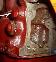
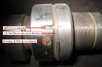
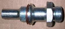 One key point in the oil flow path is at the right rear corner of the engine block. Here there is a special fitting where the external oil line connects. The longitudinal oil gallery passes through the cross drilling at the back of the block where this fitting connects. The fitting has a tubular end which enters the block to receive the oil from the cross drilling. This tubular end also blocks the path from the cross drilling to the oil gallery in the block. If a fitting is installed which does not have this extended tubular end, oil can pass directly from the cross drilling into the gallery in the block, completely bypassing the oil filter (and oil cooler if fitted). The cooler return line fitting at the filter mount is such a fitting without the tubular extension.
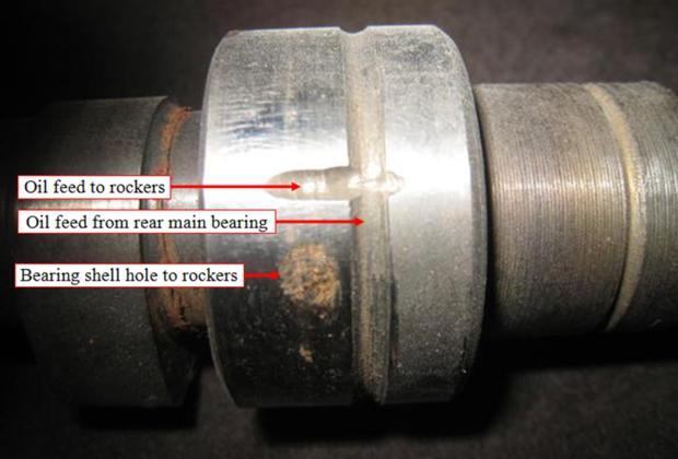
It is possible (but not likely) for the main bearings to be completely starved of oil and still have pressure on the gauge. There would have to be an obstruction in the flow path between the oil gallery and the main bearings. One way this could happen would be for the bearing shells to be lacking the oil supply hole that receives oil from the engine block, but every main bearing set I have seen has the hole in the center of every bearing shell, the upper and lower shells being identical. It's hard to imagine enough gunk left in a freshly rebuilt engine to actually clog up the supply holes to the bearings. Another unlikely possibility would be for the crankshaft bearing journals to be machined one or two thousandths of an inch oversize, or for the bearing shell to be one or two thousandths of an inch undersize, such that there is no clearance for the oil to pass through the bearing.
Oil gallery plugs (usually press fit brass and sometimes threaded steel) are used to close ends of drilled oil holes where oil should not flow out. There are at least four brass oil gallery plugs inside the B-series engine, a few threaded plugs on the outside, and two pressed steel plugs in the ends of the valve rocker shaft. Some of these plugs are external, and if left out would result in pressurized oil loss to the outside of the engine. Some of these plugs are internal and if left out would result in oil bypassing freely back into the engine oil sump. In either case, there would be a dramatic reduction of oil pressure.
End of answers to the original questions. Another article OF-102 discusses the relationship between oil pressure, flow, and lubrication of the moving engine parts, and also the advantage (or lack thereof) of a high volume oil pump and higher oil pressure.
|