The MGA With An Attitude
CAM SPROCKET ALIGNMENT, Standard -- CM-105
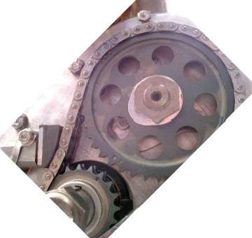
 The Workshop Manual touches on this item in Section A.17, removing and replacing the timing chain. Pay attention to the Book method for adjusting shims behind the crankshaft sprocket. Placing a straightedge across the face of the sprockets, use a feeler gauge to measure the gap between the straight edge and the crank sprocket. It then instructs to subtract 0.005-inch from thickness of the feeler gauge when determining how much to shim the sprocket, but it doesn't say why. Reason is because the crank sprocket is 0.010" thinner than the cam sprocket. I measured mine to be 0.612" for the cam sprocket and 0.602" for the crank sprocket. To get the sprockets centered with the timing chain you need to leave 0.005" gap between the straightedge and the crank sprocket. When running the chain will be guided by the larger cam sprocket, and the crank sprocket should not touch the chain side links.
The next trick they don't mention is that you have to remove the woodruff key(s) from the crankshaft to change the shims, so hopefully you can get it right the first time and not have to R&R the sprockets and keys again. When in doubt, measure thickness of cam sprocket and crank sprocket first.
You can install the sprockets without chain and with no shims, which should position the crank sprocket slightly aft of the cam sprocket. Lay a straight edge across the face of the sprockets, holding it in firm contact with the cam sprocket. Use a feeler gauge to measure any gap you may find between the straight edge and face of the crank sprocket. Rotate the cam a few times in 1/4 turn increments and measure again. This is to assure the cam sprocket is running true with no wobble. Add or remove shims behind the crank sprocket as required to position the face of the crank sprocket 0.005" behind the face of the cam sprocket.
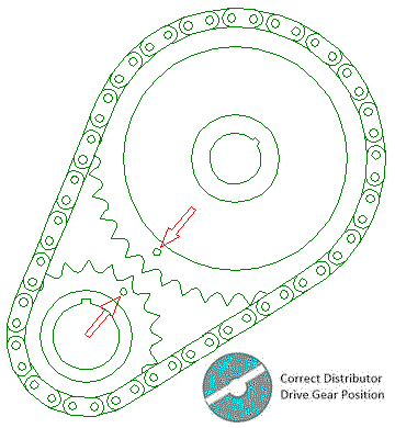
Install the crank key(s) before final installation of the sprockets and timing chain (and camshaft locktab and nut). By the Book, align punch marks on the sprockets adjacent to each other when installing the chain. Tighten the camshaft sprocket retaining nut, and fold up the locktab. At this point the book doesn't bother to mention that this orientation positions the camshaft with #1 intake and exhaust valves both partly open at top of exhaust stroke for #1 cylinder. This is important later when it is time to install the distributor drive gear, in which case you have to rotate the crankshaft one full turn to put #1 piston at top of compression stroke (where you want the spark to occur).
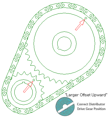
Addendum, May 15, 2009: It has been brought to my attention (thanks to Walt Westhoff) that there is an error in the "MGA Owners Workshop Manual" by Haynes (commonly known as the Haynes MGA manual). Issue is by Haynes Publishing Group 1980, 1989. In the instructions for installing the distributor drive gear, Chapter 1, Section 56, it incorrectly states, "if the timing cover has not been refitted, the distributor drive can be refitted when the dots on the timing wheels are adjacent to each other". It further states, "Rotate the crankshaft so that No. 1 piston is at TDC on its firing stroke (the dots in the timing gears will be adjacent to each other)". Both of these statements are wrong. Correct information is that when #1 piston is at TDC at beginning of firing stroke (end of compression stroke), the punch marks on the sprockets will be in line with the shafts, but the punch mark on the cam sprocket will be farther away at top (1:00 o'clock position), not adjacent to the punch mark on the crank sprocket.

Sprocket position for timing chain installation.
#1 piston is at TDC after exhaust stroke.
|

Sprocket position for distributor drive gear installation.
#1 piston is at TDC after compression stroke.
|
|