The MGA With An Attitude
TURN SIGNAL SWITCH - TS-101 - Pg 3 of 6
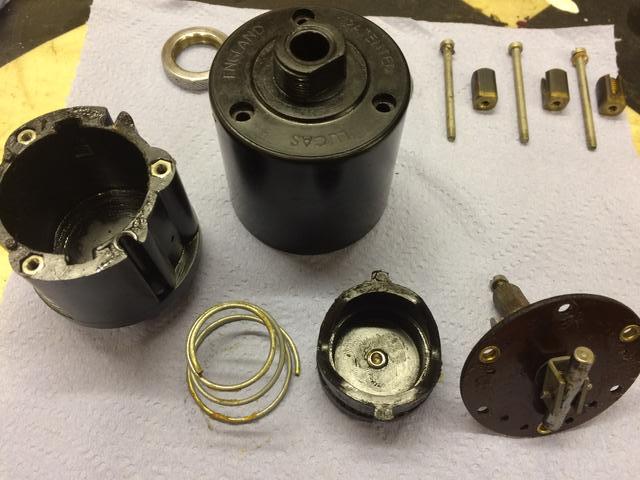
The second part of disassembly is to remove the three long screws. When you do this, the switch plate comes off the front of the unit, wire terminal blocks come off the back, and the pneumatic plunger and spring will come out of the inside. You can also remove the small set screw from the center back of the housing. Note also that there are three small hex nuts that can fall out at this time, having been residing in the front of the vacuum body and held in place by the switch cover. These nuts are the anchor points for the first three screws that were holding the outer front cover.
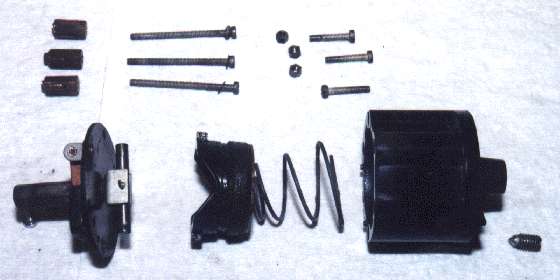
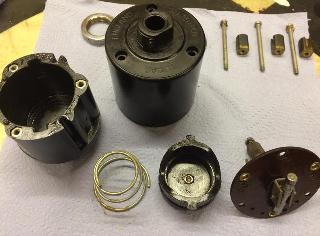 Notice here that the manual actuation shaft on the front is connected to a yoke holding a small cross bar. This bar rides in large "V" notches in the piston, such that the piston is pushed back as the bar is rotated. When the manual lever is released the piston can return forward and push the small bar back around to its center position shutting off the switch. The speed of this return is regulated by vacuum inside the body of the unit, this vacuum being gradually relieved by air being vented in through the center port at the rear of the unit, and that air flow rate being controlled by the small set screw.
|