The MGA With An Attitude
ELIMINATING the TURN SIGNAL RELAY - TS-201
Using 1600 type rear lights with a 1500 wiring harness.
This article would be of interest to someone considering converting an MGA 1500 model to a 1600 model, where the primary difference in the electrical system is the brake light and turn signal wiring.
At 10:09 AM 9/13/04 -0400, Garreth Smith wrote:
"I am in the process of re-building a 1959 MGA that is a bit of a basket case. The rear lights have already been converted to a 1600, and the front indicator has been changed to orange. Is it possible to remove the direction indicator relay?"
Yes. However, .... there's more to the conversion than that. The turn signal and brake light circuits represent the entire difference in the wiring harnesses between the 1500 and 1600 model (aside from some Lucar connectors on the 1600 model). The 1500 only has 2 wires going to the rear of the car for left and right turn signal lamps, which are also used as brake lights. The 1600 needs 3 wires there, as the brake lights are on a separate circuit from the turn signals. So the wiring harness is different, and the 1600 setup wants a new harness. If you are restoring the car and are replacing the wiring harness anyway, no problem, just buy the harness for the 1600 model.
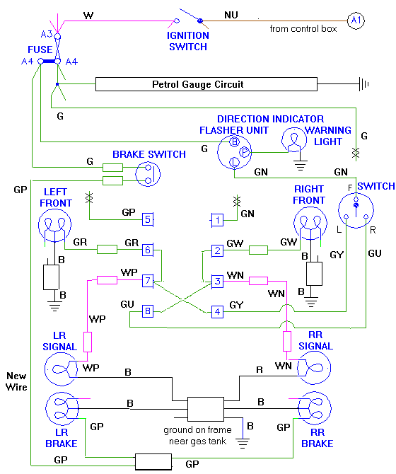
Compare these two diagrams:
Switched On and Fused - 1500 -
Switched On and Fused - 1600
For the 1500, output from the flasher unit and output from the brake switch feed to the relay, the turn signal switch takes power from the fuse and outputs to the relay. When the relay operates it disconnects one brake lamp from the brake light circuit and connects it to the front lamp and to the flasher output. For the 1600, the brake light switch powers the (separate) brake lamps directly. Output from the flasher unit feeds the turn signal switch which powers the corner signal lamps directly. No relay needed.
If you do not want to replace the wiring harness, but want to use the 1500 harness for the 1600 setup, you will need to make some wiring changes. See the modified wiring diagram below. Start by installing the extra lamp fixtures at the rear containing the single filament bulb for the turn signals (the round lamps on top of the 1600 type plinths). Transfer the turn signal wires from the double filament bulb to the single filament bulb on each side. Change the 4-way snap connector with black wires to a 6-way snap connector, and add the black ground wires for the new lamp fixtures. At this point turn signals and brake lights will work on the single filament fixture, same as they did previously on the other bulb.
Disconnect the original green/purple wire from the brake switch to the relay, as it will no longer be used. Run one new (green/purple) wire from the brake light switch down the side harness to the connector bundle behind the RR wheel. There you use a double (4-way) female snap connector to branch the brake light wire to run to the 2 original double filament brake lamps. Brake lights will now work on the 2-filament bulbs as original, and only the turn signals work on the new single filament bulbs. At that point you could stop, and just continue to use the relay and the rest of the 1500 wiring harness as is. But considering that the relay can be a bit bothersome from time to time, you may prefer to eliminate it.

To eliminate the relay, start by disconnecting the green/brown wire from the flasher unit, and run a new (green/brown) wire from the output of the flasher unit to feed the turn signal switch. Disconnect the green wire from the switch, as it is no longer used.
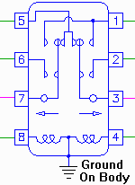
Disconnect wires from relay terminals 2, 3 & 8, and connect them together.
Disconnect wires from relay terminals 6, 7 & 4, and connect them together.
Flasher output now goes to the switch which now powers the corner lights directly. Turn signals will then work without the relay.

Addendum August 6, 2015:
If you want to leave the relay box in place, you can use it for a terminal block. You can move wires 3 and 8 to terminal 2, and move wires 4 and 7 to termianl 6. Having disconnected power to the trigger terminals, the relay will not click, and terminals 2 and 6 are open circuit (not connected to anything internally).
|

