The MGA With An Attitude
STARTER SWITCH Wiring for MGA - SS-104
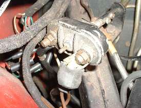
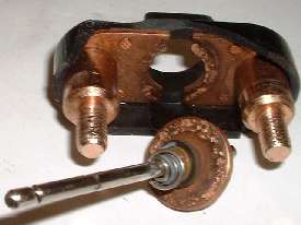
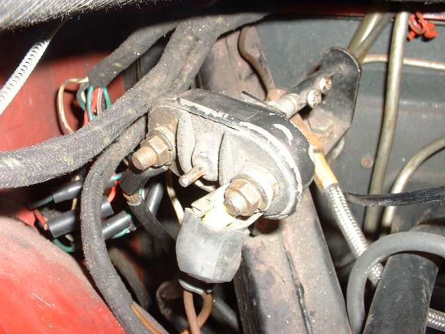
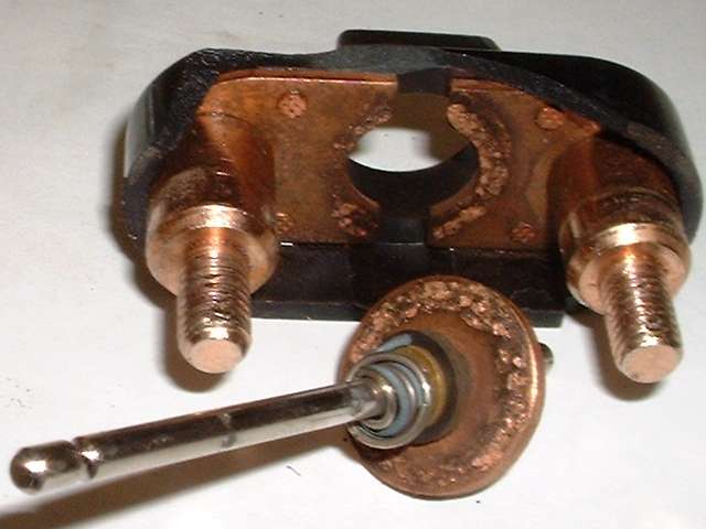
The MGA starter switch is a simple device, at least in theory. It is a mechanical contactor operated with a manual pull cable. Internally it throws a heavy copper washer across a pair of heavy copper plates to make the contact that will carry about 200 amps of current to crank the starter motor. One key part of the design is that the heavy washer must be electrically isolated (insulated) from the pull spindle. When used regularly it tends to be self cleaning by way of a bit of electrical arcing that will burn the metal contacts to base metal each time it is used. It is generally very reliable as my original starter switch has been going strong for more than 50 years and 325,000 miles. The switch has a thin metal shell crimped in place to hold the assembly together and to provide a mounting collar. Inside the metal shell is a thicker plastic (phenolic) insulating shell, and on the back there is a thick insulating face plate to enclose the inner bits. The two terminal posts must be electrically isolated from the metal case (measure infinite resistance from post to case).
Originally there were only three wires connected to this switch, a heavy cable from the battery, another heavy cable going to the starter motor, and one fat brown wire from the battery cable going to terminal "A" on the control box. The two heavy cables carry the high current required to run the starter motor. The fat brown wire carries power for everything else electrical in the car, including charging current from the generator back into the battery. The two fat cable ends and terminals were originally covered with rubber boots to prevent accidental electrical shorting.
If left to sit in storage for many years the copper contacts might corrode to the point of having high resistance contacts that might interfere with passing enough current to run the starter efficiently. To check for this condition you could disconnect one battery cable, connect an ohm meter on the two connector studs, operate the switch and check the contact resistance. Dealing with high current and low voltage requires extremely low contact resistance. For example, suppose the starter draws 200 amps and we must limit voltage loss across the switch to 1 volt. P=E.I means power equals voltage times current. One volt drop with 200 amps of current would generate 200 watts of heat in the switch contacts. P=I^2.R relates power to resistance rather than to voltage. Rearranging this equation to solve for resistance makes it R=P/I^2. For 200 watts and 200 amps the resistance works out to be 0.005 ohms for maximum allowed resistance. This small value is difficult to measure with a hand held ohm meter, as you have issues with contact resistance between the test probes and slightly corroded switch connector posts.
Another way (maybe easier) to check on the health of the switch is to measure voltage drop across that switch while it is carrying the high current used to run the starter motor. To do this set the volt meter on the 0-20 volt scale and connect the test probes to the two studs on the starter switch. Here you should be reading available battery voltage as the starter motor has such little internal resistance as to serve as a ground connection for the volt meter. Then with ignition switch OFF (transmission in neutral and parking brake set), operate the starter switch to crank the engine while observing the volt meter. With about 200 amps flowing through the switch, if the switch resistance is indeed no more than 0.005 ohms, the volt meter reading should drop to no more than 1 volt maximum. If you see higher voltage, that means the switch has too much internal resistance and it will be dissipating too much of the voltage needed to run the starter motor.
Another way to test for a bad starter switch is to simply short across the terminal posts with a heavy conductor. You can use the handles of a slip-joint pliers to do this, but be prepared for the tool to get hot quickly. Otherwise disconnect the starter cable from the terminal post, and touch it directly to the battery cable on the other post. If the starter spins well this way but not with power going through the starter switch, then you have a bad switch.
First approach to a high resistance starter switch is to simply operate it repeatedly with the normal electrical load in hopes that internal arcing will burn off any accumulated corrosion leaving clean contact surfaces. This does usually work if there is nothing else wrong with the switch. If you ever have in internal short from either switch terminal to the metal shell (or pull cable) the input voltage will drop dramatically and the switch (or pull cable) will get very hot as it will be dissipating all of the energy the battery can produce. In that case you need a new switch.
The common way to connect the starter switch is to put the battery cable on terminal nearest the inner fender and the starter cable on the terminal nearest the engine. I like to do it the other way around with the battery cable on the inboard terminal. This is a convenient place to connect a battery charger or jumper cable(s) if you don't want to open the battery cover behind the seats, and the inboard terminal is much easier to reach without shorting out your electrical clip.
This battery terminal post on the starter switch is also a convenient connection point for connecting any additional wires you may use for add-on accessories needing high current supply. For instance, if you install high power driving lights or a motor driven compressor for an air horn, you would run a heavy wire from the battery cable to a relay, and use smaller wires from a switch to trigger the relay. If you install a high current alternator in place of the original low current generator you might connect a larger wire directly from the alternator output to the battery cable. If you install a cigar-lighter type power jack under the dash you might also connect that directly to the battery cable at this same terminal point.
If you connect too many fat brown wires to the battery cable at this point you may have a hard time installing the rubber boot to protect the terminal post. In that case you might consider installing an insulated terminal post on the inner fender and connecting the battery cable there along with all of your extra fat brown wires. Then run a short length of battery cable from that terminal post to the starter switch, and wiring at the starter switch can get back to the normal three wires. A terminal post on the inner fender may also be placed in a more convenient location for connecting a jumper cable or battery charger clip.
|